USB Temperature Logger With Some Extra Tricks

Many of us electronics hacker types tend to have at least the same common equipment on our benches, namely a multimeter, an oscilloscope, some sort of adjustable power supply, and maybe a logic analyzer. These are great tools covering many bases, but dealing with temperature measurements is often neglected. A sudden need for such often results in just buying a either dedicated measurement unit, or some cheap eBay thermocouple board and just rolling with a few hacks. [Jana Marie Hemsing] had a need for measuring the thermal side of things, and got fed up with hacking with piles of boards, and designed herself a proper instrument for the task.

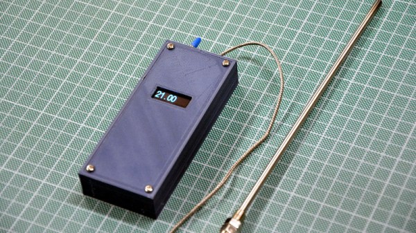
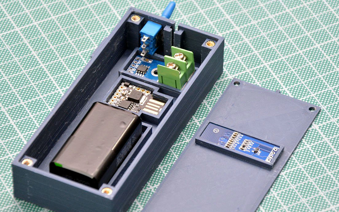
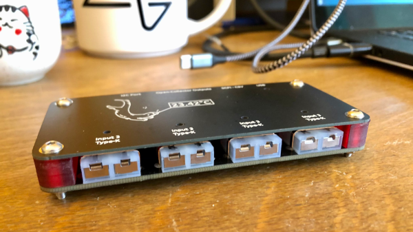
The result is a very tidy four-channel thermocouple frontend, feeding the data into the host computer via USB. Each of the four channels can either be a K-type input or a NTC thermistor input, decided at board assembly time, but you could just build two units with four channels of each and cover all bases. The K-type thermocouple input is based around the MAX31855 series device. While the ‘KASA’ suffixed device is probably most common, if you need to dedicate some channels to handling one of the other six or so other common thermocouple types, that just needs the appropriate MAX31855 variant dropping in, and you’re good to go.

For the controller, [Jana] has chosen the common STM32F0x microcontroller, which handles all the USB protocol side of things. The extra functionality added allows direct driving of a heater controller via the DRV8837 H-Bridge, with a extra few open collector outputs for other things you might want to drive. This allows the logger to function as a kind-of thermal IO device. Firmware is written in good old fashioned STM32 HAL, using the standard STM32CubeMX and the GCC toolchain. It looks like the Makefile came via the STM32 Project Generator route. The firmware has a neat trick up its sleeve too; with a flick of the switch on the back, the firmware can switch between outputting CSV data over a standard USB CDC link (a virtual serial port), or it can present a SCPI terminal interface, enabling integration into existing SCPI-based test flows. Nice work!

We’ve seen a few logging projects on these fair pages, like this battery powered ESP32 logger device. If IoT logging is more your thing, here you go.

Build Your Own High-Temp Oven Thermometer

Looking to keep an eye on the temperature inside his wood-fired pizza oven, [Giovanni Bernardo] decided to skip the commercial offerings and build his own high-temperature thermometer using a type-K thermocouple. The end result is a no-nonsense handheld unit with a surprisingly low part count that, at least in theory, can read temperatures as high as 1023.75°C. Though we hope he’ll be pulling the pizza out long before that.

Inside the 3D printed case we find just a handful of components. The 0.91″ OLED display mounted in the front panel is wired to a Digispark ATtiny85 development board, which in turn is connected to a MAX6675 breakout board. This takes the input from the thermocouple probe and converts it into a digital signal that can be read over SPI with an Arduino library from Adafruit. Rather than going through the added complication of adding a rechargeable pack, [Giovanni] is running this thermometer from a standard 9 V battery thanks to the 5 V regulator built into the Digispark.

We especially appreciate the attention to detail [Giovanni] put into his case design. Each component is nestled into a perfectly formed pocket in the bottom of the box, and he’s even gone through the trouble of using heat-set inserts for the front panel screw holes. It would have been quicker and easier to just model up a basic box and hot glue his components in place, but he took the long way around and we respect that.

This project is another example of an interesting principle we’ve observed over the years. Put simply, if somebody is going through this much trouble to check an object’s temperature, there’s a higher than average chance they intend on eating it at some point.

Gardening As Nature Intended, With An Arduino

We’re not exactly what you’d call naturalists here at Hackaday, so to us, the idea that hot pepper seeds need to germinate in hot conditions sounds suspiciously like a joke. The sort of thing somebody might tell you right before they try to sell you an elevator pass, or cram you into a locker. But we don’t think [Dean] would have gone through so much trouble if it wasn’t true. You’re still not going to sell us an elevator pass, though. Not again.

According to [Dean], the Carolina Reaper pepper seeds he bought from Puckerbutt Pepper Company (truly a name you can trust) recommend that they be germinated at a temperature between 80 and 85 degrees Fahrenheit for up to eight weeks. To make sure they were maintained at the optimal temperature for as long as possible, he decided to get a heating pad he could place under the seeds to keep them warm. He just needed some way to make sure the heat only kicked on once the soil temperature fell out of the sweet spot.

To get an accurate reading, [Dean] ended up going with a waterproof K-type thermocouple connected to a SainSmart MAX6675 module that could be buried amongst the seeds. When the soil temperature drops below 82.5 F, it kicks on the heating mat through an IoT Relay by Digital Loggers. He even added in a capacitive soil moisture sensor and a couple of LEDs so he could tell from across the room if he needed to water what he loving refers to as his “Hell Berries”

Looking back through the archives, we see a considerable overlap between hacking and gardening. Since success demands the careful control and monitoring of a myriad of variables, it seems the sort of thing that’s ripe for gloriously over-engineered automation. Especially if you’re trying to get the things to sprout off-world.

A Compensated Thermocouple Amp, Ready For Arduino

When you want to measure temperature with an Arduino or other microcontrollers, there are a ton of options for sensors. Temperature chips and sensor modules abound, some with humidity sensors built-in and all with easy interfacing and an expansive supporting code library. But dip one of those sensors into, say, molten aluminum, and you’ve got a problem.

If you’re measuring something hot, you need a thermocouple. Trouble is, the signal from a thermocouple is pretty small, and needs amplification and compensation before being fed into the ADC of a typical microcontroller. Unable to find a commercial amp to meet his needs, [MonkHelios] built his own thermocouple amp for microcontrollers. The design is centered around an LTC2053 instrumentation amp, which does the job of converting the K-type thermocouple’s 40.6μV/°C output to a nicely scaled 10mV/°C range, just right for ADC consumption. He also thoughtfully included an LT1025 cold-junction compensator; thermocouple amps are referenced to 0°C, so the compensator measures the actual temperature of the cold end of the junction and scales the output accordingly. The whole amp is nicely laid out on a DIY single-sided PCB with meticulously applied solder mask — this is one of the nicest home-etched boards we’ve seen in a long time.

[Bil Herd] designed a similar thermocouple amp not too long ago himself, so you might check that out too.  Or maybe you need the basics of instrumentation amps? Our “Beyond Measure” series will get you started.

A Wireless Wood Stove Monitor

[Michel] has a wood stove in his basement for extra heat in the winter. While this is a nice secondary heat source, he has creosote buildup in the chimney to worry about. [Michel] knows that by carefully monitoring the temperature of the gases in the chimney, he can hit the sweet spot where his fire burns hot enough to keep the creosote under control and cool enough that it doesn’t burn down the house. To that end, he built a wireless wood stove monitor.

The first version he built involved an annoying 20 foot run between the basement and living room. Also, the thermocouple was mounted on the surface and made poor contact with the chimney. Wood Stove Monitor 2.0 uses a probe thermometer on an Exhaust Gas Temperature (EGT) thermocouple to measure the temperatures. The intel is fed to a thermocouple amplifier to provide a cold-compensation reference. This is shielded so that radiant heat from the stove doesn’t compromise the readings. An nRF24L01+ in the basement monitoring station communicates with another module sitting in the living room display so [Michel] can easily find out what’s going on downstairs. When it’s all said and done, this monitor will be part of a bigger project to monitor power all over the house.

Interested in using a wood stove to help heat your house? Why not build your own?

Android-based Reflow Brings Solder Profiles To Your Lab

[Andy Brown] is a prolific hacker and ends up building a lot of hardware. About a year back, he built a reflow oven controller. The board he designed used a large number of surface mount parts. This made it seem like a chicken or egg first problem. So he designed a new, easy to build, Android based reflow controller. The new version uses just one, easy to solder surface mount part. By putting in a cheap bluetooth module on the controller, he was able to write an app which could control the oven using any bluetooth enabled Android phone or tablet.

The single PCB is divided into the high voltage, mains powered section separated from the low power control electronics with cutout slots to take care of creepage issues. A BTA312-600B triac is used to switch the oven (load) on and off. The triac is controlled by a MOC3020M optically isolated triac driver, which in turn is driven by a micro controller via a transistor. The beefy 12Amp T0220 package triac is expected to get hot when switching the 1300W load, and [Andy] works through the math to show how he arrived at the heat sink selection. To ensure safety, he uses an isolated, fully encased step down transformer to provide power to the low voltage, control section. One of his requirements was to detect the zero cross over of the mains waveform. Using this signal allows him to turn on the triac for specific angle which can be varied by the micro controller depending on how much current the load requires. The rectified, but unfiltered ac signal is fed to the base of a transistor, which switches every time its base-emitter voltage threshold is reached.

For temperature measurement, [Andy] was using a type-k thermocouple and a Maxim MAX31855 thermocouple to digital converter. This part caused him quite some grief due to a bad production batch, and he found that out via the eevblog forum – eventually sorted out by ordering a replacement. Bluetooth functions are handled by the popular, and cheap, HC-06 module, which allows easy, automatic pairing. He prototyped the code on an ATmega328P, and then transferred it to an ATmega8 after optimising and whittling it down to under 7.5kb using the gcc optimiser. In order to make the board stand-alone, he also added a header for a cheap, Nokia 5110 display and a rotary encoder selector with switch. This allows local control without requiring an Android device.

Gerbers (zip file) for the board are available from his blog, and the ATmega code and Android app from his Github repo. The BoM list on his blog makes it easy to order out all the parts. In the hour long video after the break, [Andy] walks you through solder tip selection, tips for soldering SMD parts, the whole assembly process for the board and a demo. He then wraps it up by connecting the board to his oven, and showing it in action. He still needs to polish his PID tuning and algorithm, so add in your tips in the comments below.

Continue reading “Android-based Reflow Brings Solder Profiles To Your Lab”

How To Build A Thermocouple Amplifier

A Thermocouple is a terrific way to measure temperature. The effects of temperature change on dissimilar metals produces a measurable voltage. But to make that measurement you need an amplifier circuit designed for the thermocouple being used.

Linear Technology LTC 1049 Low Power Zero-Drift Operational Amplifier with Internal Capacitors
Linear Technology LTC 1049 Low Power Zero-Drift Operational Amplifier
with Internal Capacitors

While researching “Zero Drift Amplifiers” as a follow-up to my video on Instrumentation Amplifiers I noticed the little schematic the front page of the LTC1049 datasheet which is shown here. I thought it was an ideal example of an analog application where some gain and some “gain helper” were needed to accomplish our useful little application of amplifying a thermocouple probe.

In the video I don’t really talk much about the thermocouples themselves other than the type I see most of the time which is type K. If you’re not already familiar with the construction of these probes you can find an informative write-up on thermocouples and the different types on the Wikipedia page and you might also want to check out the Analog Devices app note if you would like to know more. What I will cover is a reliable and precise way to read from these probes, seen in the video below and the remainder of the post after the break.

Continue reading “How To Build A Thermocouple Amplifier”