The Nintendo Game Boy and its many permutations represent one of the most well-known and successful gaming platforms ever produced. There was a decades-long stretch of time where the most popular kid in the lunch room was the one who brought in their Game Boy so the rest of the class could huddle around and check out the latest Pokemon title.
But those days are long gone, and now these once-coveted handhelds can be had for a song on the second-hand market. Which makes it the perfect time to check out this project [kgsws] released recently that allows you to interface the Game Boy LCD with the ESP32 or the Raspberry Pi. In the most basic of applications, it lets you push video from your Linux computer out to the Game Boy LCD over WiFi. But as the video below illustrates, that’s just the tip of the iceberg.
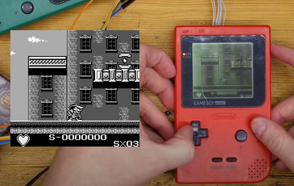 With the ESP32 wired between the handheld’s LCD and main PCB, the microcontroller can also act as a capture device using I2S camera mode. Compared to what ends up showing on the handheld’s LCD, the recorded gameplay [kgsws] shows off looks fantastic. Visuals are crisp and fluid, and naturally devoid of the Game Boy’s iconic (if slightly nauseating) greenish tint.
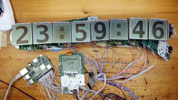
The project also includes the capability to control an array of Game Boy LCDs, which allows for some interesting possibilities. The image can be stretched to cover multiple displays, which [kgsws] demonstrates by playing a game on 3 x 3 grid of salvaged panels, but each LCD also can be controlled individually as is the case with the large digital clock seen above.
Whether you’re looking for a way to capture gameplay on the real hardware, or want to run RetroPie on a real Game Boy screen, we’re excited to see what folks come up with using this project.
Continue reading “ESP32 And Raspberry Pi Take Over Game Boy LCD”