An LED bulb with integrated controller chip

Reverse-Engineering A Two-Wire LED Strip Protocol

Although Christmas may be several weeks behind us, various colorful LED contraptions can nowadays be found in our houses at any time of year. [Tim] got his hands on an LED curtain that came with a remote control that allows the user to set not only the color of the LEDs as a whole but also to run simple animations. But these were not your standard WS2812B strips with data lines: all the LEDs were simply connected in parallel with just two wires, so how was this even possible?

An oscilloscope screenshot showing the data protocol used in an LED string
The LED string protocol is very simple, with one address field and one data field.

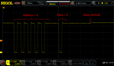
[Tim] hooked up his oscilloscope to the LED strings to find out how they worked, detailing the results in a comprehensive blog post. As it turns out, the controller briefly shorts the LED strip’s supply voltage to generate data bits, similar to the way old pulse-dialing phones worked. A tiny chip integrated into each LED picks up these pulses, but retains its internal state thanks to a capacitor that keeps the chip powered when the supply line goes low.

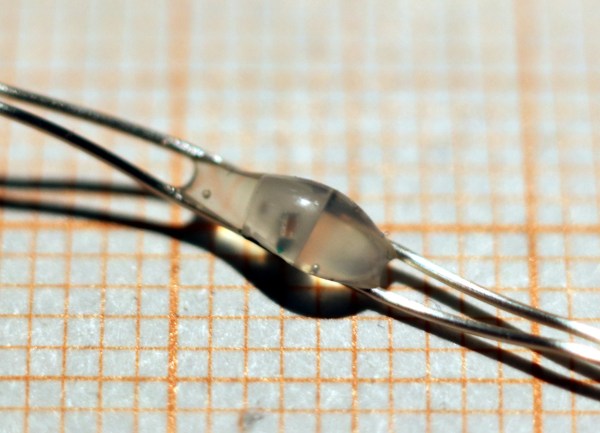
After reverse-engineering the protocol, [Tim] went on to implement a similar design using an ATMega328P as a controller and an ATtiny10 as the LED driver. With just a few lines of code and a 100 nF buffer capacitor across the ATtiny’s power pins, [Tim] was able to turn an LED on and off by sending pulses through the supply lines. Some work still needs to be done to fully implement a protocol as used in the LED strings, but as a proof-of-concept it shows that this kind of power-line communication is possible with standard components.

We’ve seen projects that send signals down a two-wire LED chain before, although as an add-on to a more ordinary LED strip. [Tim] is not the first to reverse-engineer poorly documented LED strip protocols, but probably won’t be the last either.

LED Stick Person Costume Lights Up The Night

Sometimes a simple idea can yield fantastic results. A few runs of LED strips fastened to a black hoody and sweatpants and just like that…a LED stick person costume for Halloween. The creator of the “Glowy Zoey” [Royce] originally put together some glow in the dark stick person suits to stand out when hitting the slopes at night. Now he’s taken that simple idea for a costume and made a small business out of it.


“I had a lot of extra parts laying around. I gathered everything up and got to work soldering.”  – Royce Hutain

The suits themselves consist of button snaps and ribbon loops sewn into a pattern that routes the LED strips around the jacket’s hood and down each arm. To make the lighting effect pop, an all black plastic mask is used to cover the wearer’s face. It wouldn’t be that much a stretch to substitute EL wire in place of the LED strips if one were so inclined. We’d wager a number of you could pull this off straight out of the junkbox.

The Glowy Zoey stick figure suits even received some mainstream television press a few years ago when they were featured on Jimmy Fallon’s Late Night show. Note that visiting the Glowy Zoey website may take you back a bit since it features one of those autoplay jingles that were so prevalent in the Web 1.0 days. In fact the same jingle is used in the video below from their YouTube channel:

Continue reading “LED Stick Person Costume Lights Up The Night”

A Look At Chinese Value Engineering

Seventy cents doesn’t buy you a lot these days. Maybe some sweets or candies at most. How about a string of LEDs that you can use to decorate your home during the festive season? [Amaldev] was curious to know what was, or wasn’t, inside these blinky LED strings which made them so cheap. He’s done a Christmas LED Light Teardown and shows how blinky LED string lights can be built with the bare minimum of components.

The string he purchased had 28 LEDs – seven each in four colors, a controller box with one push button and a  power cord. Without even knowing what is inside the controller box, the cost of the product seems astonishing based on this BoM. The single push button cycles through eight different light patterns for each press. It even has a faux CE mark for the supply plug. Cracking open the case, he finds that the controller board is sparsely populated with just seven through hole components and a COB (chip on board) module. A simple, 8-bit, 8-pin microcontroller is possibly what controls the device.

[Amaldev] sketches out a schematic to figure out how it works. There are two arms with 14 LEDs of alternating colors, each of which is controlled by an SCR. Two GPIO output pins from the COB control the gates of each of these SCR’s. The button is connected to a GPIO input, and a second input is connected to the AC supply via a current limiting resistor. Most likely, this is used to determine the zero crossing of the waveform so that the COB can generate the appropriate trigger signals for the gate outputs.

It is unlikely that these products are manufactured using automated processes. The PCB production could be automated, but soldering all the wires, fitting it all in the enclosure and preparing the LED string itself would require manual labor. At US$ 0.7 retail on the street, it is difficult to imagine the cost breakdown even when the quantities are in large numbers. Maybe a combination of cheap components, recycled or rejected parts (mains cord/enclosure), lack of safety and protection measures (no fuses, no strain reliefs) and reducing the component BoM to an absolute, bare minimum, coupled with very high volumes lets them pull it off? What are your thoughts – chime in with comments.