Logic analyzer capture, showing the rails constantly oscillating at a high rate

When Your Level Shifter Is Too Smart To Function

By now, 3.3V has become a comfortable and common logic level for basically anything you might be hacking. However, sometimes, you still need to interface your GPIOs with devices that are 5 V, 1.8 V, or something even less common like 2.5 V. At this point, you might stumble upon autosensing level shifters, like the TXB010x series Texas Instruments produces, and decide that they’re perfect — no need to worry about pin direction or bother with pullups. Just wire up your GPIOs and the two voltage rails you’re good to go. [Joshua0] warns us, however, that not everything is hunky dory in the automagic shifting world.

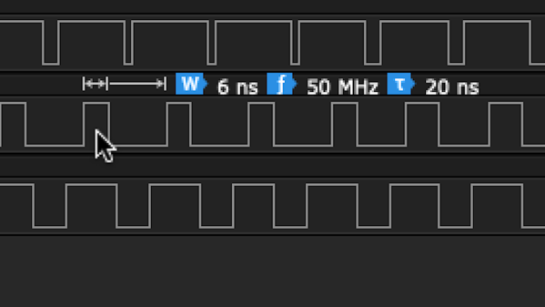
During board bring-up and multimeter probing, he found that the 1.8 V-shifted RESET signal went down to 1.0V — and its 3.3 V counterpart stayed at 2.6V. Was it a current fight between GPIOs? A faulty connection? Voltage rail instability? It got more confusing as the debugging session uncovered the shifting operating normally as soon as the test points involved were probed with the multimeter in a certain order. After re-reading the datasheet and spotting a note about reflection sensitivity, [Joshua0] realized he should try and probe the signals with a high-speed logic analyzer instead.

Continue reading “When Your Level Shifter Is Too Smart To Function”

Probes connected from a Pi Pico board to the SPI flash chip, with other end of the probes connected tot the level shifter circuit resistors

Motherboard Revived With Simplest 1.8V SPI Shifter Ever

If you have ever had to fix a modern desktop motherboard, you might have noticed that the BIOS (UEFI) SPI flash is 1.8V – which means you can no longer use a Raspberry Pi or a CH341 adapter directly, and you’d need to use a 1.8V level shifter of some sort. Now, some of us can wait for a 1.8V level shifter adapter from an online store of your choosing, but [treble] got a “BIOS flash failed” motherboard from Facebook Marketplace, and decided to make it work immediately.

She tells us a story about reviving the motherboard, and there’s one thing she shows that is interesting in particular – a very simple way to level shift 3.3V signals from a serprog-flashed Pi Pico down to the 1.8V that the flash chip required, something you are guaranteed to be able to build out of the parts in your parts bin, only requiring nine resistors and an NPN transistor. If you ever need to reflash BIOS on a modern motherboard, take note. As for 1.8V rail, she ended up tapping the 1.8V power pin of the SPI chip the motherboard itself to power the chip while programming it.

In the end, after swapping the two BIOS chips places and fixing a broken trace mishap, the motherboard booted, and works wonderfully to this day, a much-needed upgrade to [treble]’s toolkit that allows her to do RISC-V cross-compiling with ease nowadays. This is not the first time we see people reflash modern boards with 1.8V chips – if you want to learn more, check out this incredibly detailed writeup! Need to do some further debugging? Use your Pico as a POST card!

FET: Fun Endeavors Together

Last time, we’ve looked over FET basics, details, nuances and caveats. Basics aren’t all there is to FETs, however – let’s go through real-world uses, in all their wonderful variety! I want to show you a bunch of cool circuits where a friendly FET, specifically a MOSFET, can help you – and, along the way, I’d also like to introduce you to a few FETs that I feel like you all could have a good long-term friendship with. If you don’t already know them, that is!

Driving Relays

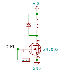
Perhaps, that’s the single most popular use for an NPN transistor – driving coils, like relays or solenoids. We are quite used to driving relays with BJTs, typically an NPN – but it doesn’t have to be a BJT, FETs often will do the job just as fine! Here’s an N-FET, used in the exact same configuration as a typical BJT is, except instead of a base current limiting resistor, we have a gate-source resistor – you can’t quite solder the BJT out and solder the FET in after you have designed the board, but it’s a pretty seamless replacement otherwise. The freewheel (back EMF protection) diode is still needed for when you switch the relay and the coil produces wacky voltages in protest, but hey, can’t have every single aspect be superior.

The reason you can drive it the same way is quite simple: in the usual NPN circuit, the relay is driven by a 3.3 V or a 5 V logic level GPIO, and for small signal FETs, that is well within Vgs. However, if your MCU has 1.8 V GPIOs and your FET’s Vgs doesn’t quite cut it, an NPN transistor is a more advantageous solution, since that one will work as long as you can source the whatever little current and the measly 0.7 V needed.

Continue reading “FET: Fun Endeavors Together”

Logging Into Linux With A 1930s Teletype

Buried deep within all UNIX-based operating systems are vestiges of the earliest days of computing, when “hardware” more often than not meant actual mechanical devices with cams and levers and pulleys and grease. But just because UNIX, and by extension Linux, once supported mechanical terminals doesn’t mean that getting a teletype from the 1930s to work with it is easy.

Such was the lesson learned by [CuriousMarc] with his recently restored Model 15 Teletype; we covered a similar Model 19 restoration that he tackled. The essential problem is that the five-bit Baudot code that they speak predates the development of ASCII by several decades, making a converter necessary. A task like that is a perfect job for an Arduino — [Marc] put a Mega to work on that — but the interface of the Teletype proved a bit more challenging. Designed to connect two or more units together over phone lines, the high-voltage 60-mA current loop interface required some custom hardware. The testing process was fascinating, depending as it did on an old Hewlett-Packard serial signal generator to throw out a stream of five-bit serial pulses.

The big moment came when he used the Teletype to log into Linux on a (more or less) modern machine. After sorting out the mysteries of the stty command, he was able to log in, a painfully slow process at 45.5 bps but still a most satisfying hack. The ASCII art — or is it Baudot art? — is a nice bonus.

We love restorations like these, and can practically smell the grease and the faint tang of ozone around this device. We’re not thrilled by the current world situation, but we’re glad [CuriousMarc] was able to use the time to bring off a great hack that honors another piece of our computing history.

Continue reading “Logging Into Linux With A 1930s Teletype”

Taking It To Another Level: Making 3.3V Speak With 5V

If your introduction to digital electronics came more years ago than you’d care to mention, the chances are you did so with 5V TTL logic. Above 2V but usually pretty close to 5V is a logic 1, below 0.8V is a logic 0. If you were a keen reader of electronic text books you might have read about different voltage levels tolerated by 4000 series CMOS gates, but the chances are even with them you’d have still used the familiar 5 volts.

This happy state of never encountering anything but 5V logic as a hobbyist has not persisted. In recent decades the demands of higher speed and lower power have given us successive families of lower voltage devices, and we will now commonly also encounter 3.3V or even sometimes lower voltage devices. When these different families need to coexist as for example when interfacing to the current crop of microcontroller boards, care has to be taken to avoid damage to your silicon. Some means of managing the transition between voltages is required, so we’re going to take a look at the world of level shifters, the circuits we use when interfacing these different voltage logic families.

Continue reading “Taking It To Another Level: Making 3.3V Speak With 5V”