Flat Transformer Gives This PCB Tesla Coil Some Kick

Arguably, the most tedious part of any Tesla coil build is winding the transformer. Getting that fine wire wound onto a suitable form, making everything neat, and making sure it’s electrically and mechanically sound can be tricky, and it’s a make-or-break proposition, both in terms of the function and the aesthetics of the final product. So this high-output printed circuit Tesla should take away some of that tedium and uncertainty.

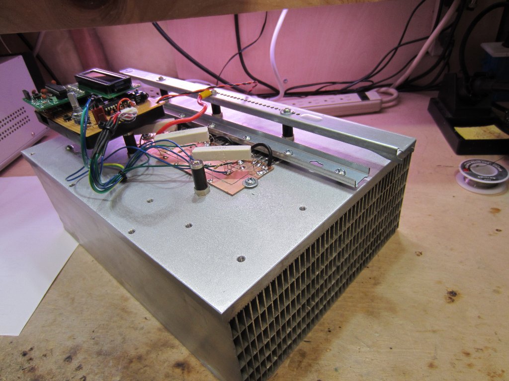
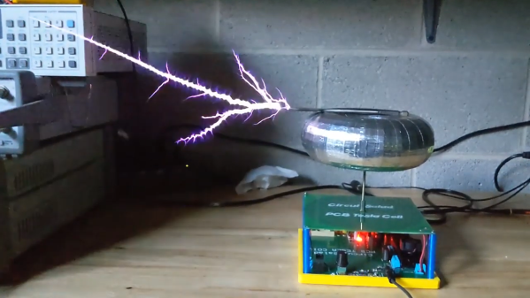
Now, PCB coils are nothing new — we’ve seen plenty of examples used for everything from motors to speakers. We’ve even seen a few PCB Tesla coils, but as [Ray Ring] points out, these have mostly been lower-output coils that fail to bring the heat, as it were. His printed coil generates some pretty serious streamers — a foot long (30 cm) in some cases. The secondary of the coil has 6-mil traces spaced 6 mils apart, for a total of 240 turns. The primary is a single 240-mil trace on the other side of the board, and the whole thing is potted in a clear, two-part epoxy resin to prevent arcing. Driven by the non-resonant half-bridge driver living on the PCB below it, the coil can really pack a punch. A complete schematic and build info can be found in the link above, while the video below shows off just what it can do.

Honestly, for the amount of work the PCB coil saves, we’re tempted to give this a try. It might not have the classic good looks of a hand-wound coil, but it certainly gets the job done. Continue reading “Flat Transformer Gives This PCB Tesla Coil Some Kick”

Know The Load With This Simple Microcontroller CPU Meter

How do you tell how much load is on a CPU? On a desktop or laptop, the OS usually has some kind of gadget to display the basics. On a microcontroller, though, you’ll have to roll your own CPU load meter with a few parts, some code, and a voltmeter.

We like [Dave Marples]’s simple approach to quantifying something as complex as CPU load. His technique relies on the fact that most embedded controllers are just looping endlessly waiting for something to do. By strategically placing commands that latch an output on while the CPU is busy and then turn it off again when idle, a PWM signal with a duty cycle proportional to the CPU load is created. A voltage divider then scales the maximum output to 1.0 volt, and a capacitor smooths out the signal so the load is represented by a value between 0 and 1 volt. How you display the load is your own choice; [Dave] just used a voltmeter, but anything from an LED strip to some kind of audio feedback would work too.

Still just looking for a load meter for your desktop? Take your pick: an LED matrixold-time meters, or even Dekatrons.

Improving Active Loads

[Texane]’s job requires testing a few boards under a set of loads, and although the lab at work has some professional tools for this it seemed like a great opportunity to try out the Re:load 2. It’s a nifty little active load that’s available can of course be improved with an injection of solder and silicon.

While the Re:load 2 is a nice, simple device that can turn up to 12 Watts directly into heat, it’s not programmable. The ability to create and save load profiles would be a handy feature to have, so [Texane] took a Teensy 3.1 microcontroller and installed a resistor divider in front of the Re:load’s amplifier. A simple script running on a computer allows [Texane] to set the amount of current dumped and automate ramps and timers.

There is a more fundamental problem with the Re:load; the lowest possible current that can be dumped into a heat sink is 90mA. [Texane] replace the amplifier with a zero-drift amp that brought that 90mA figure down to 7mA.

Of course the Re:load and Teensy 3.1 are sold in the Hackaday store, but if you’re looking for a ready-built solution for a computer-controlled active load you can always check out the Re:load Pro, a fancy-smanchy model that has an LCD. The Pro costs more, and [Texane] just told you how to get the same features with the less expensive model we’re selling, though…

Arduino Electronic Load

A Simple Programmable Electronic Load Using The Arduino

Some projects are both educational and useful. We believe that [Jasper’s] Arduino based electronic load is one of those project.

[Jasper’s] electronic load can not only act as a constant current load, but also as a constant power and constant resistive load as well. The versatile device has been designed for up to 30V, 5A, and 15W. It was based on a constant current source that is controlled by a DAC hooked up to the Arduino. By measuring both the resulting voltage and current of the load, the system can dynamically adapt to achieve constancy. While we have seen other Arduino based constant loads before, [Jasper’s] is very simple and straight forward compartively. [Jasper] also includes both the schematic and Arduino code, making it very easy to reproduce.

There are tons of uses for a voltage controlled current source, and this project is a great way to get started with building one. It is an especially great project for putting together your knowledge of MOSFET theory and opamp theory!

An Arduino Programmable Load

Having a big block of hot to dump current into is a very useful thing to have if you’re testing batteries, power supplies, high power LEDs, electroplating, or any thing else that would normally require a huge resistor. [Jakub] found himself in need of an electronic load, and instead of a transistor and a pot, decided to make something more automatic: a programmable load built around an Arduino shield.

The idea behind this load is pretty simple: connect a device to a FET and shunt resistor to measure current. Drive the gate of the FET with an op-amp that maintains either constant current or constant voltage. Control everything with a DAC, and you have a programmable load controlled by an Arduino.

With such a small form factor, getting rid of all that heat was bound to be a problem. For this, [Jakub] is using a 50×50 mm BGA style heat sink with a 5V fan. If it’s good enough for a big CPU, it should be able to handle dumping 70 Watts into a FET. There’s also a conservative application of thermal paste and a very small thermistor underneath the FET that’s able to be read by the Arduino. It might slowly heat up your room, but it’s not going to catch fire.

With the Arduino sketches [Jakub] wrote for his load he was able to characterize a pair of Idea batteries and figure out how much charge a three-year-old recyclable battery had. It’s a great piece of work, and if [Jakub] is willing to go through the hassle of a Kickstarter, it would make a fine crowdfunded product.

Building A DC Constant Current/Power Electric Load

By just looking at the picture above, we’re pretty sure that most Hackaday readers will have guessed by now that much power can be dissipated by this electric load. For those who don’t know, an electric load (or dummy load) is a device used to simulate a load on a system for testing purposes. This is quite handy when measuring battery capacities or testing power supplies.

The heart of the device that [Kerry] designed is based on 6 power MOSFETs, a few operational amplifiers and an Arduino compatible ATmega328p microcontroller. Sense resistors are used to measure how much current is passing through the MOSFETs (and therefore the load), the MCP4921 Digital to Analog Converter (DAC) from microchip is used to set the current command, and the load’s voltage is measured by the ATmega ADC. Measuring the latter allows a constant power load mode (as power = current * voltage). In his article, [Kerry] shows that he can simulate a load of up to 200W.

Continue reading “Building A DC Constant Current/Power Electric Load”