Friday Hack Chat: Logic Noise

If you like your synthesizers glitchy, squawky, or simply quick-and-dirty, you won’t want to miss this week’s Hack Chat with Hackaday’s own [Elliot Williams], because he’ll be brain-dumping everything he knows about making music with 4000-series CMOS logic chips. Break out your breadboards!

Continue reading “Friday Hack Chat: Logic Noise”

Glitchy Synthesizer Meets Honeycomb LED Matrix

Don’t watch [Jason Hotchkiss]’s video if flashing lights or bleepy-bloopy synthesizer noises give you seizures. Do watch, however, if you’re interested in a big honeycomb-shaped LED matrix being driven at audio frequencies through a dedicated square-wave synthesizer that’s built in.

The LED panel in question is housed in a snazzy laser-cut, honeycomb-shaped bezel: a nice change from the standard square in our opinion. The lights are 1/2 watt (whoa!) whites, and the rows and columns are driven by transistor drivers that are in turn controlled by shift registers. We’re not entirely sure how the matrix is driven — we’d love to see a circuit diagram — but it looks like it’s some kind of strange, non-scanning mode where all of the column and row drives are on at once. Whatever, it’s art.

And it’s driven by logic chips making audio-frequency square waves. Two of these are fed into an LFSR and into an R-2R DAC and then into the shift registers. The output is chaos, but the audio and the visuals do seem to influence each other. It’s an audio-visual embodiment of some of my wildest Logic Noise fantasies. Pretty cool. Enjoy the video.

Continue reading “Glitchy Synthesizer Meets Honeycomb LED Matrix”

32C3: 20 Oscillators In 20 Minutes

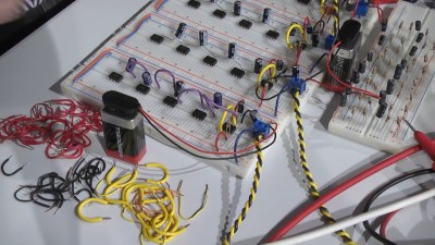
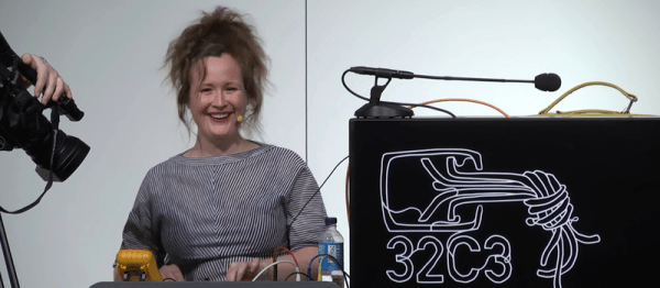
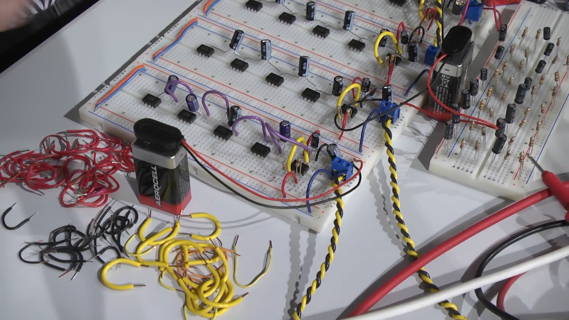
In terms of implausible stand-up comedy, [Darsha]’s “20 Oscillators in 20 Minutes” is pretty far out there. First of all, she’s sitting down, with googly eyes on her multimeter, and five breadboards and a mess of 9V batteries laid out in front of her. “Has anybody built electronics before? Has anybody built electronics in front of this many people before? Yeah, so you’d better f**king be nice.” And she’s off!

twenty_oscillators-shot0012“Square waves are really good for your speakers.” And a few seconds later, a lub-dub beat-frequency oscillator filled the hall. And then there’s the stand-up clichés: “Anyone in the audience from Norway?!” And “Anyone know what chip I’m using here?” (The 555.) A heckler, or participant, shouts up “What are you doing?” She responds “Building this!” and shows a sketch of the basic layout.

She baits the audience — “Do you want to ask me about duty cycles?” — and tells stories: “And then one time the solder fell in my lap and burned through my crappy jeggings. Who knows what jeggings are? Whooo!!” All the while the clicking gets louder and more complicated.

Then there’s the suspense. “11 minutes left? Shit, I dunno if I’m going to make it this time!” She’s visibly panicked. A question: “How do you protect the outputs from overvoltage?” “I don’t. (pause, laughter) I use some filter caps and just, well, hope that you guys have good insurance.”

Nearing the home stretch, there’s this quasi-rhythmic ticking and pulsing slowly building up in the background. She plugs in another capacitor, and the crowd spontaneously applauds. A little bit later, she shouts “Is it loud enough?” over the din and turns it down. At the end, the timing’s getting really tight, and she calls up someone to help from the audience.

We won’t spoil it, naturally. You’ll just have to watch it run to the end. We laughed, we cried. It was better than Schroedinger’s cats.

(We’d use hex inverters.)

Logic Noise: Digital To Analog With An R-2R DAC

Making sound with digital logic usually calls for a Digital to Analog converter. Building one can be very simple, and the sound quality out of an R-2R Ladder is actually pretty good.

In the last edition of Logic Noise, we built up a (relatively) simple VCO — voltage-controlled oscillator — that had roughly one-volt-per-octave response. I even demonstrated it working mostly in tune with another synth’s keyboard. But what if you don’t have a control-voltage keyboard sitting around or you want to combine all of the logic-based circuits that we’ve been building with other circuits under voltage control? That’s where the digital to analog (DAC) voltage converter comes in.

Continue reading “Logic Noise: Digital To Analog With An R-2R DAC”

Logic Noise: Playing In Tune With An Exponential VCO

Last session, we use the cheap and cheerful 4046 Phase-locked Loop chip as a simple voltage-controlled oscillator (VCO). It was dead simple, in fact, because the chip has a VCO already built in. There’s one big drawback of the 4046’s VCO; the pitch changes linearly with the control voltage. Ideally, as we’ll discuss in the next sections, we’d like the frequency to be an exponential function of the control voltage (CV), and that’s going to mean a little bit of analog circuitry.

René Schmitz has a fantastic exponential VCO design that’s almost a perfect fit for the Logic Noise series — it’s built with a minimum of parts, it’s a little bit rough around the edges, and at its core is a 4000-series CMOS chip that’s normally used for digital logic applications. The only drawback, from our perspective, is that it uses a dual (positive and negative) power supply. We’ll hack our way around that, and ignore some of René’s otherwise worthwhile refinements in the name of doing something truly quick and dirty. We’ll get 95% of the results with 70% of the work, although it’s easy enough to add on the rest if it strikes your fancy.

Continue reading “Logic Noise: Playing In Tune With An Exponential VCO”

Logic Noise: 4046 Voltage-Controlled Oscillator, Part One

In this session of Logic Noise, we’ll be playing around with the voltage-controlled oscillator from a 4046 phase-locked loop chip, and using it to make “musical” pitches. It’s a lot of bang for the buck, and sets us on the path toward much more interesting circuits in the future. So watch the intro video right after the break, and we’ll dig straight in.

Continue reading “Logic Noise: 4046 Voltage-Controlled Oscillator, Part One”

Logic Noise: Ping-pong Stereo, Mixers, And More

So far on Logic Noise, we’ve built up a bunch of sound-making voices and played around with sequencing them. The few times that we’ve combined voices together, we’ve done so using the simplest possible passive mixer — a bunch of resistors. And while that can work, we’ve mostly just gotten lucky. In this session, we’ll take our system’s output a little bit more seriously and build up an active mixer and simple stereo headphone driver circuit.

For this, we’ll need some kind of amplification, and our old friend, the 4069UB, will be doing all of the heavy lifting. Honestly, this week’s circuitry is just an elaboration of the buffer amplifiers and variable overdrive circuits we looked at before. To keep things interesting we’ll explore ping-pong stereo effects, and eventually (of course) put the panning under logic-level control, which is ridiculous and mostly a pretext to introduce another useful switch IC, the 4066 quad switch.

At the very end of the article is a parts list for essentially everything we’ve done so far. If you’ve been following along and just want to make a one-time order from an electronics supply house, check it out.

klangorium
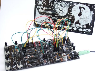
If you’re wondering why the delay in putting out this issue of Logic Noise, it’s partly because I’ve built up a PCB that incorporates essentially everything we’ve done so far into a powerhouse of a quasi-modular Logic Noise demo — The Klangorium. The idea was to take the material from each Logic Noise column so far and build out the board that makes experimenting with each one easy.

Everything’s open and documented, and it’s essentially modular so you can feel free to take as much or as little out of the project as you’d like. Maybe you’d like to hard-wire the cymbal circuit, or maybe you’d like to swap some of the parts around. Copy ours or build your own. If you do, let us know!

OK, enough intro babble, let’s dig in.

Continue reading “Logic Noise: Ping-pong Stereo, Mixers, And More”