Logic Analyzer Add-on For The MSP430 Launchpad

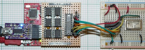
Here’s a 6-channel logic analyzer shield for the MSP430 Launchpad. It manages an eyebrow-raising 16 million samples per second. The prototype seen above is made on a hunk of protoboard with point-to-point soldering. [oPossum] did lay out a PCB — which is just 50mmx50mm — but has not had any produced quite yet.

He calls it the LogicBoost, and based it on the the LogicShrimp design. The sextuplet of 8-pin chips are all SPI RAM. These are responsible for storing the samples, with a 74HC573 latch routing the traffic. The MSP430 chip provides the SPI clock, and the Launchpad’s virtual com port can be used to push the data to a computer for graphing. That’s a bit slow so [oPossum] also included an optional header for an FTDI board that will do a faster job. The sample rate can be adjusted by tweaking the internal oscillator setting of the chip; there’s plenty to choose from so it will work for just about any purpose (as long as you don’t surpass the 16 Msps speed limit).

[via Dangerous Prototypes]

Using The Parallel Port As A Logic Sniffer

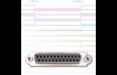
[Fernando] wrote in to share his take on building a logic analyzer. He’s using the parallel port to capture data and feed it to the display software of your choice.

The method depends on a custom kernel which alters the way the parallel port works. The kernel he compiled includes a method of intercepting the signals coming in from the hardware, passing that data to the /dev/parport* as it should, but also sending a copy to /dev/parportsnif*. It also creates a log file which is in the OpenBench Logic Sniffer format for easy use with various display software.

Of course this is easiest to use with a Linux system, but can also be run as a virtual machine under Windows. We’d plan on using a virtual machine within Linux as well since this is a custom kernel and will probably only see occasional use.

HEX Out Reveals The Secrets Your Data Bus Holds

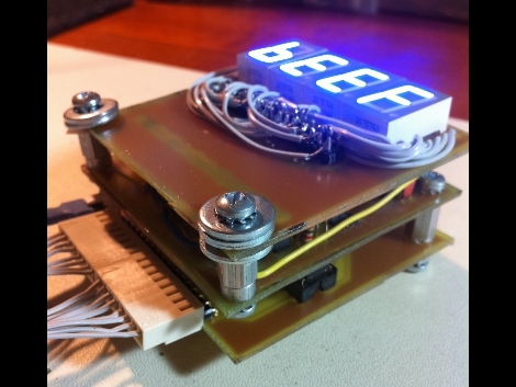
[Quinn Dunki] is looking to augment the tools she has available at her electronics bench and built the HEX Out as a mock-logic sniffer. The device reads 8 or 16-bit inputs, showing the current state of those connections on a 7-segment display. This requires that you’re comfortable reading Hex codes, but if you’re not it’s almost like studying flash cards; before long you’ll be able to read them without thinking about it.

She’s blogging about the design and build process in three parts. The link above is the first installment where she shares the development process for the top layer which hosts the display hardware. The other two parts should be up for your enjoyment in the next couple of weeks.

You’ll notice her design on this portion of the project still requires a lot of point-to-point soldering, even though she etched her own circuit boards. We didn’t look too closely, but it seems this would be worth going to the trouble of etching a double-sided board if you can.

UPDATE: Part Two is now available