Listening To Mains Power

There’s a lot you can tell by looking at the waveform of your mains power. There are harmonics, transient changes, and periodic fluctuations that are correlated to the demand on the grid itself. Frequency shifts will tell you how fast or slow your clocks are running, and someone probably has a poorly isolated power line communication thing somewhere in your neighborhood. There’s a lot you can learn by looking at the waveform coming out of your outlets, but how do you tap into that? [David] is doing it with a PC sound card and some really interesting hardware.

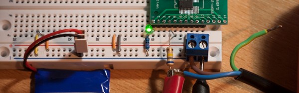
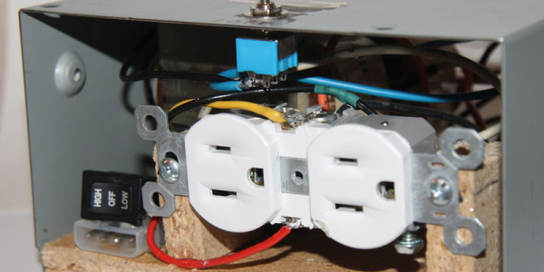
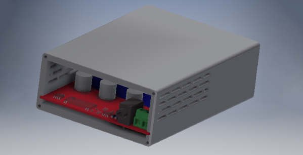
The Grid 2 Audio module is [David]’s entry to this year’s Hackaday Prize, and it consists of three main parts. The first is the mechanical part of the design. This comes in the form of an IEC power socket with a built-in switch, fuse, and illumination. Of course, you could simply buy one of these, but [David] is teaching himself Autodesk Inventor, and you have to start somewhere. The second part of this build is the PCB power supply and mains input. This is basically a pair of transformers, a PCB, and a whole lot of isolation to make this a safe board. The third part is a signal conditioning board that sends the waveform to a 3.5mm jack, for easy processing with any audio capture hardware.

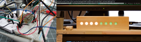
The hardest part of this board is, by far, the PCB design, and for that [David] went all out. There are some big, meaty traces on this thing and real separation between the high voltage and low voltage portions of the board. The end result is something that sends the mains waveform to an audio card for easy processing with MATLAB, and all the goodies that come from that.

Tricking A Vintage Clock Chip Into Working On 50-Hz Power

Thanks to microcontrollers, RTC modules, and a plethora of cheap and interesting display options, digital clock projects have become pretty easy. Choose to base a clock build around a chip sporting a date code from the late 70s, though, and your build is bound to be more than run-of-the-mill.

This is the boat that [Fran Blanche] finds herself in with one of her ongoing projects. The chip in question is a Mostek MK50250 digital alarm clock chip, and her first hurdle was find a way to run the clock on 50 Hertz with North American 60-Hertz power. The reason for this is a lesson in the compromises engineers sometimes have to make during the design process, and how that sometimes leads to false assumptions. It seems that the Mostek designers assumed that a 24-hour display would only ever be needed in locales where the line frequency is 50 Hz. [Fran], however, wants military time at 60 Hz, so she came up with a circuit to fool the chip. It uses a 4017 decade counter to divide the 60-Hz signal by 10, and uses the 6-Hz output to turn on a transistor that pulls the 60-Hz output low for one pulse. The result is one dropped pulse out of every six, which gives the Mostek the 50-Hz signal it needs. Sure, the pulse chain is asymmetric, but the chip won’t care, and [Fran] gets the clock she wants. Pretty clever.

[Fran] has been teasing this clock build for a while, and we’re keen to see what it looks like. We hope she’ll be using these outsized not-quite-a-light-pipe LED displays or something similar.

Continue reading “Tricking A Vintage Clock Chip Into Working On 50-Hz Power”

The Electrical Outlet And How It Got That Way

Right now, if you happen to be in Noth America, chances are pretty good that there’s at least one little face staring at you. Look around and you’ll spy it, probably about 15 inches up from the floor on a nearby wall. It’s the ubiquitous wall outlet, with three holes arranged in a way that can’t help but stimulate the facial recognition firmware of our mammalian brain.

No matter where you go you’ll find those outlets and similar ones, all engineered for specific tasks. But why do they look the way they do? And what’s going on electrically and mechanically behind that familiar plastic face? It’s a topic we’ve touched on before with Jenny List’s take on international mains standards. Now it’s time to take a look inside the common North American wall socket, and how it got that way.

Continue reading “The Electrical Outlet And How It Got That Way”

Mains Clocking A Microcontroller

[Lujji] is playing around with the STM8 microcontroller. In reviewing the official documentation for this chip, he read the external clock can be a sine wave, a triangle wave, or a square wave with a 50% duty cycle. The minimum CPU frequency is 0 Hz. [Lujji] doesn’t have a signal generator, and presumably, he’s all out of crystals. He does have mains AC, though, so why not clock a microcontroller with wall power?

Using mains power as a frequency standard is a concept a hundred years old. Synchronous motors turn at a rate proportional to the mains frequency, and this has been used in clocks for decades. If you’re really clever, you can clock digital circuits with mains AC, but we’ve never seen someone replace a tiny crystal in a microcontroller circuit with mains power.

After an experiment to prove the concept, [Lujji] went on to construct a circuit that wasn’t as dumb as connecting the microcontroller directly to a wall socket. The direct approach didn’t work that well anyway — the STM8 didn’t like low frequency clocks with slow edges. [Lujji] needed a clock with cleaner edges, and a 555 configured as a comparator fit the bill.

The completed circuit sends mains power through an optocoupler to drive a 555 configured as a comparator. The output is a clean 50Hz clock that is connected to the OSCIN pin on an STM8. This is now a chip running at 50Hz, and yes, it works. [Lujji] set up a circuit to write ‘Hello World’ on an old Nokia LCD. That took about three minutes. It works, though, even though it’s completely useless. Maybe this can be applied to some novel timekeeping similar to that one-instruction-per-day clock we looked earlier in the year.

Hacking On The Weirdest ESP Module

Sometimes I see a component that’s bizarre enough that I buy it just to see if I can actually do something with it. That’s the case with today’s example, the ESP-14. At first glance, you’d ask yourself what AI Thinker, the maker of many of the more popular ESP8266 modules, was thinking.

The ESP-14 takes the phenomenally powerful ESP8266 chip and buries it underneath one of the cheapest microcontrollers around: the 8-bit STM8S003 “value line” chip. Almost all of the pins of the ESP chip are locked inside the RF cage’s metal tomb — only the power, bootloader, and serial TX/RX pins see the light of day, and the TX/RX pins are shared with the STM8S. The rest of the module’s pins are dedicated to the STM8S. Slaving the ESP8266 to an STM8S is like taking a Ferrari and wrapping it inside a VW Beetle.

I had never touched an STM8 chip before, and just wanted to see what I could do with this strange beast. In the end, ironically, I ended up doing something that wouldn’t be too far out of place on Alibaba, but with a few very Hackaday twists: a monitor for our washer and dryer that reports power usage over MQTT, programmed in Forth with a transparent WiFi serial bridge into the chip for interactive debugging without schlepping down into the basement. Everything’s open, tweakable, and the Forth implementation for the STM8S was even developed here on Hackaday.io.

It’s a weird project for the weirdest of ESP modules. I thought I’d walk you through it and see if it sparks you to come up with any alternative uses for the ESP8266-and-STM8S odd couple that is the ESP-14.

Continue reading “Hacking On The Weirdest ESP Module”

Tripping Out: A Field Guide To Circuit Protection

My introduction to circuit protection came at the tender age of eight. Being a curious lad with an inventive – and apparently self-destructive – bent, I decided to make my mother a lamp. I put a hose clamp around the base of a small light bulb, stripped the insulation off an old extension cord, and jammed both ends of the wires under the clamp. When I plugged my invention into an outlet in the den, I saw the insulation flash off the cord just before the whole house went dark. Somehow the circuit breaker on the branch circuit failed and I tripped the main breaker on a 200 amp panel. My mother has never been anywhere near as impressed with this feat as I was, especially now that I know a little bit more about how electricity works and how close to I came to being a Darwin Award laureate.

To help you avoid a similar fate, I’d like to take you on a trip (tee-hee!) through the typical household power panel and look at some of the devices that stand at the ready every day, waiting for a chance to save us from ourselves. As a North American, I’ll be focusing on the residential power system standards most common around here. And although there is a lot of technology that’s designed to keep you safe as a last resort, the electricity in your wall can still kill you. Don’t become casual with mains current!

Continue reading “Tripping Out: A Field Guide To Circuit Protection”

Upcycle An Isolation Transformer

There are several reasons you should have an isolation transformer. They can prevent ground loops and also prevent a device under test from having a DC path to ground (or isolate an oscilloscope from DC ground, which can be dangerous in its own right, but that’s another discussion). [Tanner_tech] noticed that finding ballast transformers for sodium vapor street lights is getting easier as more street lights move to LED technology. What to do with these transformers? Build an isolation transformer, of course.

Of course, your dumpster transformer might be a little different than the one shown in the post (and the video, below). [Tanner] shows how to work out the leads you need. A little wood work and a PC power supply case finished the project.

Judging from the comments, some people take [Tanner’s] talk about safety as an implication that a transformer makes working on mains safe. It doesn’t. It makes it safer if you know what you are doing. Working with high voltage isn’t a place to learn by doing.

If you want some practical advice, [Jenny List] has a good read for you. You probably also ought to invest an hour in watching this video that has a lot of practical advice.

Continue reading “Upcycle An Isolation Transformer”