Exploding Multimeter Battle Royale

If you check out eBay, Amazon, or the other kinda-shady online retailers out there, you’ll quickly find you can buy a CAT III (600V) rated multimeter for under $50. If you think about it, this is incredible. There’s a lot of engineering that needs to go into a meter that is able to measure junction boxes, and factories in China are pushing these things out for an amazing price.

Over on the EEVBlog, these meters are being pushed to the limits. Last month, [joeqsmith] started a thread testing the theory that these cheap meters can handle extremely high voltages. A proper CAT III test requires a surge of electrons with a 6kV peak and a 2 ohm source. With a bunch of caps, bailing wire, JB Weld and zip ties, anyone can test if these meters are rated at what they say they are. Get a few people on the EEVBlog sending [joeqsmith] some cheapo meters, and you can have some real fun figuring out how these meters stack up.

The real experiments began with [joe smith]’s low energy surge generator, a beast of a machine that can be measured with an even beastlier high voltage scope probe. This is a machine that will send a voltage spike through anything to short out traces on poorly designed multimeters.

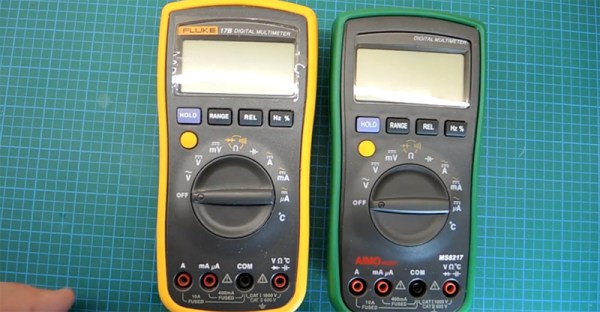
How did the cheapo meters fare? Not well, for the most part. There was, however, one exception: the Fluke 101. This is Fluke’s My First Multimeter, stuffed into a pocketable package. This meter is able to survive 12kV pulses when all but two of the other brands of meters would fail at 3kV.

What’s the secret to Fluke’s success? You only need to look at what the Fluke 101 can’t do. Fluke’s budget meter doesn’t measure current. If you ever look inside a meter, you’ll usually find two fuses, one for measuring Amps and the other for all the other functions on the scope. There’s quite a bit of engineering that goes into the current measurement of a meter, and when it goes wrong you have a bomb on your hands. Fluke engineers rather intelligently dropped current measurement from this budget meter, allowing them to save that much on their BOM.

There’s an impressive amount of data collected by [joeqsmith] and the other contributors in this thread, but don’t use this to decide on your next budget meter; This is more of an interesting discovery of how to make a product that meets specs: just cut out what can’t be done with the given budget.

Disassembled Mouse Keeps Track Of Gas Meter

After building devices that can read his home’s electricity usage, [Dave] set out to build something that could measure the other energy source to his house: his gas line. Rather than tapping into the line and measuring the gas directly, his (much safer) method was to simply monitor the gas meter itself.

The major hurdle that [Dave] had to jump was dealing with an ancient meter with absolutely no modern electronics like some other meters have that make this job a little easier. The meter has “1985” stamped on it which might be the manufacturing date, but for this meter even assuming that it’s that new might be too generous. In any event, the only option was to build something that could physically watch the spinning dial. To accomplish this, [Dave] used the sensor from an optical mouse.

The sensor is surrounded by LEDs which illuminate the dial. When the dial passes a certain point, the sensor alerts an Arduino that one revolution has occurred. Once the Arduino has this information, the rest is a piece of cake. [Dave] used KiCad to design the PCB and also had access to a laser cutter for the enclosure. It’s a great piece of modern technology that helps integrate old analog technology into the modern world. This wasn’t [Dave]’s first energy monitoring system either; be sure to check out his electricity meter that we featured a few years ago.

Meter Backlight

Adding A Backlight To A Cheap Multimeter

We don’t all need super high quality electronic testing gear. Sometimes second-hand or inexpensive equipment is accurate enough to get the job done. Though it can be a bit annoying to miss out on some of those “luxury” features. [Ekriirke] had this problem with his cheap multimeter. He wished the LCD screen had a backlight for easier visibility, so rather than upgrade to a more expensive unit he just added one himself.

After opening up the multimeter [Ekriirke] found that it ran on a single 12V battery. He realized that the simplest thing to do would be to wire up four white LEDs in series. The four LEDs were arranged within the case off to each side of the LCD, one in each corner. The leads were bent at 90 degree angles and soldered together “dead bug” style. Thin strips of copper foil tape were attached to the PCB in such a way that the anode and cathode from the LEDs would make contact when the case was closed back up.

The tape wraps around to the other side of the PCB where there was more room for the next piece of the circuit. A capacitor, resistor, and transistor are used in conjunction with a momentary switch. This circuit allows [Ekriirke] to turn on the light for about ten seconds by pressing the button one time. The circuit also runs through the meter’s dial switch, preventing the LEDs from being turned on while the meter itself is turned off.

[via Reddit]

Fail Of The Week: The Deadliest Multimeter

Need a good multimeter? The Fluke 17B is an excellent basic meter that will last your entire career. It’s also $100 USD. Need something cheaper? Allow me to introduce the AIMOmeter MS8217. On the outside, it’s a direct copy of the Fluke 17b, right down to the screen printing but understandably lacking the yellow enclosure. $30 USD will get you an exact copy of a Fluke 17B, it would seem. Right? Not a chance. [electronupdate] did a teardown of the AIMOmeter, and while this meter looks like a Fluke on the outside, it’s probably going to kill somebody.

The teardown begins with a look at the ratings on the back of this off-brand meter. It does have two fuses, but the engraving on the back strangely claims ‘Wrrebt insurance limit’. If anyone has any idea what a ‘wrrebt’ is, please leave a note in the comments. The only references to this word in Google are mis-OCRed blackletter type in a book from the early 1800s.

Opening up the meter reveals – surprisingly – two real fuses in the meter. There were no markings on the bigger fuse, which could be a problem for verifying if the fuse is of the proper value. That’s not really a problem, though: the fuse isn’t even between ground and the amp probe socket. Yes, this fuse is completely useless, and testing the resistance with the fuse out of the circuit confirms this.

After putting the meter back together, [electron] tests the accuracy of the meter. With a 1 mA current source, the mA setting seems to work, but when testing the larger Amp range of this meter, the results display in milliVolts. Don’t worry, there’s an easy fix for that: just press the dial down just right and the correct setting will be displayed. Wow.

You get what you pay for, and if you only ever use an AIMOmeter for measuring Arduinos and batteries, you might – might – be alright. This is not the kind of meter you want to measure line voltage, motors, or anything else with, though.

Power Meter

Solar Panel System Monitoring Device Using Arduino

[Carl] recently upgraded his home with a solar panel system. This system compliments the electricity he gets from the grid by filling up a battery bank using free (as in beer) energy from the sun. The system came with a basic meter which really only shows the total amount of electricity the panels produce. [Carl] wanted to get more data out of his system. He managed to build his own monitor using an Arduino.

The trick of this build has to do with how the system works. The panel includes an LED light that blinks 1000 times for each kWh of electricity. [Carl] realized that if he could monitor the rate at which the LED is flashing, he could determine approximately how much energy is being generated at any given moment. We’ve seen similar projects in the past.

Like most people new to a technology, [Carl] built his project up by cobbling together other examples he found online. He started off by using a sketch that was originally designed to calculate the speed of a vehicle by measuring the time it took for the vehicle to pass between two points. [Carl] took this code and modified it to use a single photo resistor to detect the LED. He also built a sort of VU meter using several LEDs. The meter would increase and decrease proportionally to the reading on the electrical meter.

[Carl] continued improving on his system over time. He added an LCD panel so he could not only see the exact current measurement, but also the top measurement from the day. He put all of the electronics in a plastic tub and used a ribbon cable to move the LCD panel to a more convenient location. He also had his friend [Andy] clean up the Arduino code to make it easier for others to use as desired.

Water Tank Monitoring System Is Now Slug-Proof

[Peter] is doing his part toward protecting the environment and conserving water. He’s built a rainwater collection system complete with an underground storage tank. Since he wanted to monitor the water level in the tank, he made a level indicating system. Everything was going well until one day out of nowhere it stopped working, only returning 0’s as the level. [Peter] took a look and found that I slug had made its way into the electronics enclosure and slimed up the traces on the PCB, causing short circuits.To fix the problem [Peter] decided to redesigned the system. This time it would be built into an all-weather electrical box. The system uses a standard hobby ultrasonic range finder to measure the distance from the top of the tank to the level of the water. Two holes cut into the electrical box allow the sender/receiver components to peek outside of the enclosure. Any gaps were then filled with sealant. [Peter] also added a thermistor to measure the temperature inside the tank.The sensor values are read by an Arduino and sent wirelessly to [Peter]’s computer via a pair of XBee’s and a second Arduino with an ethernet shield. The data are sent in 3 minute intervals and automatically stored in a MySQL database for quick reference of level and temperature trends. Now [Peter] can monitor his rain water remotely and adjust his usage habits accordingly. Want to read more about water tanks? Check out this overflow monitor system.

Tracking Power Usage With A Raspi

With tiny, Internet-connected computers everywhere these days, home automation is finally hitting it big. [Jelora] was looking for a few more home automation projects and realized his electric meter had a pair of ‘digital information outputs’. With a Raspberry Pi and a few bits of wire, he figured out how to read this digital output and put a log of his electricity consumption up on the web.

The digital output on [Jelora]’s meter is a bit odd; it’s 1200 bps, 7 bits per character, parity, with one stop bit. It’s also a 50 kHz AC signal for a binary ‘0’ and nothing for a binary ‘1’. To read this signal, [Jelora] is using a diode to throw out half the signal, a 6N138 optoisolator so the Pi isn’t connected directly to the meter, and a small cap to smooth out the signal. Simple, and it works.

This cleaned up signal is then connected to serial to USB chip and a PHP script scrapes the data every minute. The data received from the meter is stored in a data base along with a few other bits of information: if the meter is being charged peak or off-peak rates, and the price per kWh. All this is saved on an IDE hard drive (more reliable than the SD card, surprisingly), and a ‘electricity cost per day’ is plotted on a nifty graph and served up by the Raspberry Pi.