Bandpass Filters From The CNC Mill

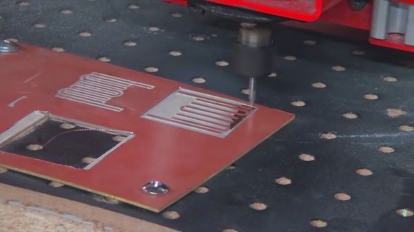
A bandpass allows a certain electrical signal to pass while filtering out undesirable frequencies. In a speaker bandpass, the mid-range speaker doesn’t receive tones meant for the tweeter or woofer. Most of the time, this filtering is done with capacitors to remove low frequencies and inductors to remove high frequencies. In radio, the same concept applies except the frequencies are usually much higher. [The Thought Emporium] is concerned with signals above 300MHz and in this range, a unique type of filter becomes an option. The microstrip filter ignores the typical installation of passive components and uses the copper planes of an unetched circuit board as the elements.

A nice analogy is drawn in the video, which can also be seen after the break, where the copper shapes are compared to the music tuning forks they resemble. The elegance of these filters is their simplicity, repeatability, and reproducability. In the video, they are formed on a CNC mill but any reliable PCB manufacturing process should yield beautiful results. At the size these are made, it would be possible to fit these filters on a business card or a conference badge.

Continue reading “Bandpass Filters From The CNC Mill”

Rapidly Prototyping RF Filters

RF filters are really just a handful of strategically placed inductors and capacitors. Yes, you can make a 1 GHz filter out of through-hole components, but the leads on the parts turn into inductors at those frequencies, completely ruining the expected results in a design.

The solution to this is microstrip antennas, or carefully arranged tracks and pads on a PCB. Anyone can build one of these with Eagle or KiCad, but that means waiting for an order from a board house to verify your design. [VK2SEB] has a better idea for prototyping PCB filters: use copper tape on blank FR4 sheets.

The first, and simplest, filter demonstrated is a simple bandstop filter. This is really just a piece of fiberglass with copper laminated to one side. Two RF connectors are soldered to the edges and a strip of copper tape strung between them. Somewhere around the middle of this copper tape, [VK2SEB] put another strip of copper tape in a ‘T’ configuration. This is the simplest bandstop filter you can make, and the beauty of this construction is that it can be tuned with a razor blade.

Of course, a filter can only be built with copper tape if you can design them, and for that [SEB] is turning to software. The Qucs project is a software tool for designing and simulating these microstrip filters, and after inputting the correct parameters, [SEB] got a nice diagram of what the filter should look like. A bit of taping, razor blading, and soldering and [SEB] had a working filter connected to a spectrum analyzer. Did it work? To a limited extent; the PCB material probably wasn’t right, and board houses are more accurate than a razor blade, but [SEB] did manage to create a 10 GHz filter out of fiberglass and copper tape.

You can check out the video for this experiment below.

Continue reading “Rapidly Prototyping RF Filters”