A Microwave Frequency Doubler

It is an age-old problem. You have a 2.5 GHz source and you want it at 5 GHz. You need a frequency doubler. [All Electronics Channel] has an interesting video that talks not only about the theory of such a device but shows a practical one made with copper strips on a blank PCB substrate.

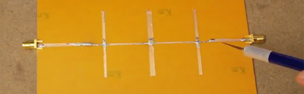
A fun thing about microwaves is that even little strips of copper are circuit elements since the wavelength at 2.5 GHz is only 12cm. That means a quarter-wave stub is only 3 cm — just over an inch.

The construction technique used is simple and, as he points out, experimenting with a real circuit will give you much more feel for how these circuits work than just reading and working out the math.

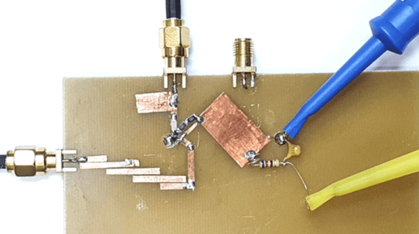
The multiplier drives an amplifier into nonlinearity which, of course, generates harmonics. Then a bandpass filter selects the second harmonic. If you haven’t dealt with stub circuits before, you might want to read up on how a piece of copper connected at one end can act like an inductor, a capacitor, or even a tuned circuit.

If you want more detail on the copper tape technique, we can help. If you don’t want to double frequency, maybe you would prefer to try voltage.

Continue reading “A Microwave Frequency Doubler”

Rapidly Prototyping RF Filters

RF filters are really just a handful of strategically placed inductors and capacitors. Yes, you can make a 1 GHz filter out of through-hole components, but the leads on the parts turn into inductors at those frequencies, completely ruining the expected results in a design.

The solution to this is microstrip antennas, or carefully arranged tracks and pads on a PCB. Anyone can build one of these with Eagle or KiCad, but that means waiting for an order from a board house to verify your design. [VK2SEB] has a better idea for prototyping PCB filters: use copper tape on blank FR4 sheets.

The first, and simplest, filter demonstrated is a simple bandstop filter. This is really just a piece of fiberglass with copper laminated to one side. Two RF connectors are soldered to the edges and a strip of copper tape strung between them. Somewhere around the middle of this copper tape, [VK2SEB] put another strip of copper tape in a ‘T’ configuration. This is the simplest bandstop filter you can make, and the beauty of this construction is that it can be tuned with a razor blade.

Of course, a filter can only be built with copper tape if you can design them, and for that [SEB] is turning to software. The Qucs project is a software tool for designing and simulating these microstrip filters, and after inputting the correct parameters, [SEB] got a nice diagram of what the filter should look like. A bit of taping, razor blading, and soldering and [SEB] had a working filter connected to a spectrum analyzer. Did it work? To a limited extent; the PCB material probably wasn’t right, and board houses are more accurate than a razor blade, but [SEB] did manage to create a 10 GHz filter out of fiberglass and copper tape.

You can check out the video for this experiment below.

Continue reading “Rapidly Prototyping RF Filters”