A Daylight-Readable Bar Graph Display In The 70s Wasn’t Cheap

The driver board with display attached; the row of lamps is visible on the right hand side.

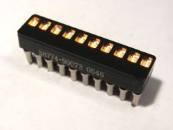
LEDs weren’t always an easy solution to displays and indicators. The fine folks at [Industrial Alchemy] shared pictures of a device that shows what kind of effort and cost went into making a high brightness bar graph display in the 70s, back when LEDs were both expensive and not particularly bright. There are no strange materials or methods involved in making the display daylight-readable, but it’s a peek at how solving problems we take for granted today sometimes took a lot of expense and effort.

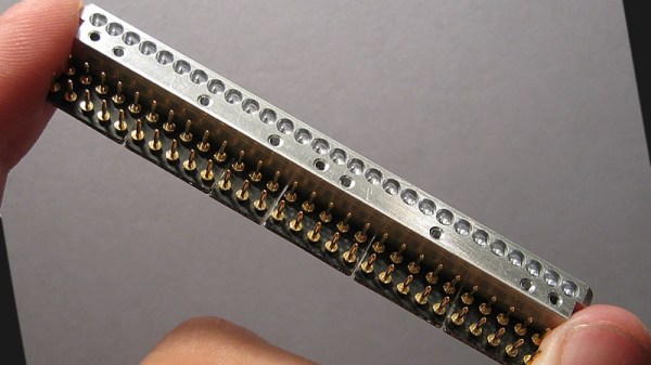
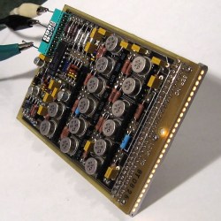
The display is a row of 28 small incandescent bulbs, mounted in a PCB and housed in a machined aluminum frame. Holes through which to view the bulbs are on both the top and front of the metal housing, which allows the unit to be mounted in different orientations. It was made as a swappable module, its 56 machined gold pins mate to sockets on the driver board. The driver board itself consists of 14 LM119 dual comparators, each of which controls two bulbs on the display.

An example of a Wamco minitron bar graph display. Each window contains an incandescent filament. [Source: industrialalchemy.org]
[Industrial Alchemy] believes that the display unit itself may have been a bit of a hack in its own way. Based on the pin spacing and dimensions of the driver board, they feel that it was probably designed to host a row of modular units known as the Wamco minitron bar graph display. An example is pictured here; they resembled DIP chips and could be stacked side-by-side to make a display of any length. Each window contained an incandescent filament in a reflective well, and each light could be individually controlled.

These minitron bar graph units could only be viewed from the top, and were apparently high in cost and low in availability. Getting around these limitations may have been worth creating this compatible unit despite the work involved.

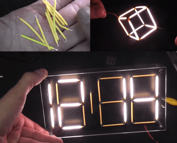
Display technology has taken many different turns over the years, and you can see examples of many of them in one place in the Circus Clock, which tells the time with a different technology for each digit: a nixie, a numitron, a 7-segment thyratron tube, a VFD, an LED dot display, and a rear projection display.

[Mike] Illuminates Us On LED Filaments

LED filaments started showing up in light bulbs a few months back. [Mike] discovered that the strips are available in bulk from ebay and Alibaba. Always keen to work with new LED technologies, [Mike] ordered a few for experimenting and posted the results on his [mikeselectricstuff] YouTube channel. He also added the information to his website.

The filaments consist of 28 LEDs connected in series. The blue LEDs are covered by the typical yellow phosphors to make them glow white. It’s interesting to note that some of the filaments use a removable silicone sleeve to hold the phosphor coating, while others are coated with a resin material. The LEDs themselves are bare dies mounted to a metal strip and joined by bond wires. The entire strip can be bent, but be careful, or you’ll break the fragile bond wires.

The strips do require a fair bit of voltage to operate. The entire strip runs best at around 75 and 10~15 mA, while putting out about 1 Watt of light. [Mike] tested a strip to destruction by pumping 40 mA through it. Predictably the strip went out when the bond wires melted. The surprising part was that the strip blinked back on as the wires cooled and re-connected. The strip and wires were working as a temperature controlled switch, similar to the bimetalic strip found in old fashioned “twinkling” incandescent Christmas lights.

Not satisfied with simple tests, [Mike] went on to build a clock using the filaments as elements of a seven segment display. Inspired by numitron and minitron displays, [Mike] built a single sided PCB which held the clock circuit on the bottom and the LED filaments on top. The filaments are spaced off the board by tall wire wrap sockets, which proved to be difficult to keep from shorting out. Texas Instruments TPIC6B595 chips were used to control the LED filaments. Logically the chip functions the same as a 75LS595, which means it can be driven with a SPI bus. The open drain outputs can handle 50 volts – which makes them perfect for this application.  The clock is tremendously bright, but there is still a bit of room for improvement. [Mike] notes that the phosphor of un-powered filaments tend to glow a bit due to light absorbed from nearby illuminated filaments. He’s experimenting with color filters to reduce this effect. At full power though, [Mike] says this clock would easily be daylight readable, and we don’t doubt it!

[Mike’s] final test was a bit whimsical – he built a cube entirely from the LED filaments. The cube looks awesome, but we can’t wait to see who will move things into the 4th dimension and build a tesseract!

Continue reading “[Mike] Illuminates Us On LED Filaments”