MOSFET Heater Is Its Own Thermostat

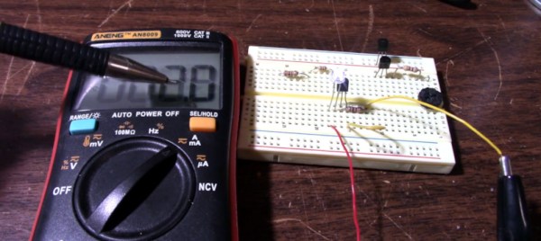
While we might all be quick to grab a microcontroller and an appropriate sensor to solve some problem, gather data about a system, or control another piece of technology, there are some downsides with this method. Software has a lot of failure modes, and relying on it without any backups or redundancy can lead to problems. Often, a much more reliable way to solve a simple problem is with hardware. This heating circuit, for example, uses a MOSFET as a heating element and as its own temperature control.

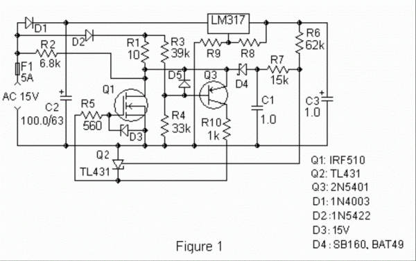
The function of the circuit relies on a parasitic diode formed within the transistor itself, inherent in its construction. This diode is found in most power MOSFETs and conducts from the source to the drain. The key is that it conducts at a rate proportional to its temperature, so if the circuit is fed with AC, during the negative half of the voltage cycle this diode can be probed and used as a thermostat. In this build, it is controlled by a set of resistors attached to a voltage regulator, which turn the heater on if it hasn’t reached its threshold temperature yet.

In theory, these resistors could be replaced with potentiometers to allow for adjustable heat for certain applications, with plastic cutting and welding, temperature control for small biological systems, or heating other circuits as target applications for this type of analog circuitry. For more analog circuit design inspiration, though, you’ll want to take a look at some classic pieces of electronics literature.

DIY Fume Extractor With ATtiny13 Speed Control

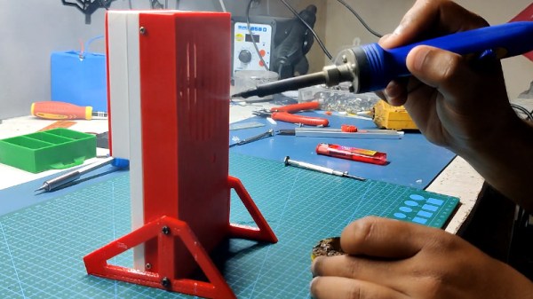
Let’s be honest, commercially-available soldering fume extractors are cheap enough that you probably don’t need to build one yourself. But it still makes for a good starter project, especially if you go out of your way to really flex your maker muscles like [Arnov Sharma] did with this tidy build.

All the hallmarks of modern hardware making are on display here — you’ve got the 3D printed enclosure, a motor salvaged from a cheap toy quadcopter, and a custom PCB which uses the ATtiny13 and an AO4406 MOSFET to implement a PWM speed control.

The first press of the button starts the motor off at max speed, but keep pushing it, and the motor’s speed will ramp down until it turns off entirely. There’s even a TP4056 charge controller to top off the internal 18650 cell when the fume extractor is connected to a USB power source.

Is it over-engineered? Perhaps. But projects like these are a great opportunity to practice your skills, whether it’s PCB design or creating bespoke 3D printed enclosures. In the era of cheap 32-bit microcontrollers, it’s also refreshing to see hackers still dragging the ATtiny from time to time.

Continue reading “DIY Fume Extractor With ATtiny13 Speed Control”

Induction Heater Uses New Coil

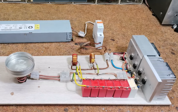
Induction cook tops are among the most efficient ways of cooking in the home that are commercially available to the average person. Since the cook surface uses magnetic fields to generate heat in the cookware itself, there is essentially no heat wasted. There are some other perks too, such as faster cooking times and more fine control, not to mention that it’s possible to build your own induction stove. All you need is some iron, wire, and a power source, and you can have something like this homemade induction cooker.

This induction heater has a trick up its sleeve, too. Instead of using an air coil to generate heat in the cookware, this one uses an iron core instead. The project’s creator [mircemk] built an air core induction stove in the past, and this new one is nearly identical with the exception of the addition of the iron core. This allows for the use of less wire, and uses a driver circuit called a Mazzilli ZVS driver running through some power MOSFETs to power the device. A couple inductors limit the current to 20A, but it appears to work just as well as the previous stove.

This build puts a homemade induction stove well within reach of anyone with an appropriate power supply and enough wire and inductors to build the coils. [mircemk] has made somewhat of a name for himself involving project that use various coils of wire, too, like this project we featured recently which uses two overlapping air-core coils to build an effective metal detector.

Continue reading “Induction Heater Uses New Coil”

Practical Transistors: JFETs

Transistors come in different flavors. Tubes used an electric field to regulate current flow, and researchers wanted to find something that worked the same way without the drawbacks like vacuum and filament voltages. However, what they first found — the bipolar transistor — doesn’t work the same way. It uses a small current to modulate a larger current, acting as a switch. What they were looking for was actually the FET — the field effect transistor. These come in two flavors. One uses a gate separated from the channel by a thin layer of oxide (MOSFETs), and the other — a junction or JFET — uses the property of semiconductors to deplete or enhance carriers in the channel. [JohnAudioTech] takes a decidedly practical approach to JFETs in a recent video that you can watch below.

The idea for the FET is rather old, with patents appearing in 1925 and 1934, but there were no practical devices at either time. William Shockley tried and failed to make a working FET in 1947, the same year the first point-contact transistor appeared, which was invented while trying to create practical FETs. In 1948, the bipolar junction transistor hit the scene and changed everything. While there were a couple of working FETs created between 1945 and 1950, the first practical devices didn’t appear until 1953. They had problems, so interest waned in the technology while the industry focused on bipolar transistors. However, FETs eventually got better, boasting both very high input impedance and simplified biasing compared to bipolar technology.

Continue reading “Practical Transistors: JFETs”

Motorcycle Regulator By Popular Demand

A few weeks ago we posted a build of an avid motorcycle enthusiast named [fvfilippetti] who created a voltage regulator essentially from the ground up. While this was a popular build, the regulator only works for a small subset of motorcycles. This had a large number of readers clamoring for a more common three-phase regulator as well. Normally we wouldn’t expect someone to drop everything they’re doing and start working on a brand new project based on the comments here, but that’s exactly what he’s done.

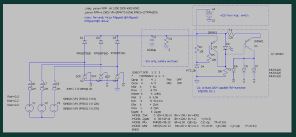
It’s important to note that the solutions he has developed are currently only in the simulation phase, but they show promise in SPICE models. There are actually two schematics available for those who would like to continue his open-source project. Compared to shunt-type regulators, these have some advantages. Besides being open-source, they do not load the engine when the battery is fully charged, which improves efficiency. The only downside is that they have have added complexity as they can’t open this circuit except under specific situations, which requires a specific type of switch.

All in all, this is an excellent step on the way to a true prototype and eventual replacement of the often lackluster regulators found on motorcycles from Aprilia to Zero. We hope to see it further developed for all of the motorcycle riders out there who have been sidelined by this seemingly simple part. And if you missed it the first time around, here is the working regulator for his Bajaj NS200.

Motorcycle Voltage Regulator Uses MOSFETs

For how common motorcycles are, the designs and parts used in them tend to vary much more wildly than in cars and trucks. Sometimes this is to the rider’s advantage, like Honda experimenting with airbags or automatic transmissions. Sometimes it’s a little more questionable, like certain American brands holding on to pushrod engine designs from the ’40s. And sometimes it’s just annoying, like the use of cheap voltage regulators that fail often and perform poorly. [fvfilippetti] was tired of dealing with this on his motorcycle, so he built a custom voltage regulator using MOSFETs instead.

Unlike a modern car alternator, which can generate usable voltage even at idle, smaller or older motorcycle alternators often can’t. Instead they rely on a simpler but less reliable regulator that is typically no more than a series of diodes, but which can only deliver energy to the electrical system while the motor is running at higher speeds. Hoping to improve on this design, [fvfilippetti] designed a switched regulator from scratch out of MOSFETs with some interesting design considerations. It is capable of taking an input voltage between 20V and 250V, and improves the ability of the motorcycle to use modern, higher-power lights and to charge devices like phones as well.

In the video below, an LED was added in the circuit to give a visual indication that the regulator is operating properly. It’s certainly a welcome build for anyone who has ever dealt with rectifier- or diode-style regulators on older bikes before. Vehicle alternators are interesting beasts in their own right, too, and they can be used for much more than running your motorcycle’s electrical system.

Continue reading “Motorcycle Voltage Regulator Uses MOSFETs”

The Q2, A PDP8-Like Discrete Transistor Computer

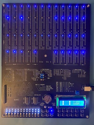
[Joe Wingbermuehle] has an interest in computers-of-old, and some past experience of building computers on perfboard from discrete transistors, so this next project, Q2, is a complete implementation of a PDP8-like microcomputer on a single PCB. Like the DEC PDP-8, this is a 12-bit machine, but instead of the diode-transistor logic of the DEC, the substantially smaller Q2 uses a simple NMOS approach. Also, the DEC has core memory, but the Q2 resorts to a pair of SRAM ICs, simply because who wants to make repetitive memory structures with discrete 2N7002 transistors anyway?

SMT components for easy machine placement

Like the PDP-8, this machine uses a bit-serial ALU, which allows the circuit to be much smaller than the more usual ALU structure, at the expense of needing a clock cycle per bit per operation, i.e. a single ALU operation will take 12 clock cycles. For this machine, the instruction cycle time is either 8 or 32 clocks anyway, and at a maximum speed of 80 kHz it’s not exactly fast (and significantly slower than a PDP-8) but it is very small. Small, and perfectly formed.

The machine is constructed from 1094 transistors, with logic in an NMOS configuration, using 10 K pullup resistors. This is not a fast way to build a circuit, but it is very compact. By looking at the logic fanout, [Joe] spotted areas with large fanouts, and reduced the pull-up resistors from 10 K to 1 K. This was done in order to keep the propagation delay within bounds for the cycle time without excessive power usage. Supply current was kept to below 500 mA, allowing the board to be powered from a USB connector. Smart!

Memory is courtesy of two battery-backed 6264 SRAMs, with the four 12-bit general purpose registers built from discrete transistors. An LCD screen on board is a nice touch, augmenting the ‘front panel’ switches used for program entry and user input. A 40-pin header was added, for programming via a Raspberry Pi in case the front panel programming switches are proving a bit tedious and error prone.

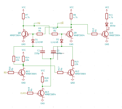
Discrete transistor D-type flip flop with indicator. Latest circuit switched to 2N7002 NMOS.

In terms of the project write-up, there is plenty to see, with a Verilog model available, a custom programming language [Joe] calls Q2L, complete with a compiler and assembler (written in Rust!) even an online Q2 simulator! Lots of cool demos, like snake. Game of Life and even Pong, add some really lovely touches. Great stuff!

We’ve featured many similar projects over the years; here’s a nice one, a really small 4-bit one, and a really big one.