We’ve all taken apart a small toy and pulled out one of those little can motors. “With this! I can do anything!” we proclaim as we hold it aloft. Ten minutes later, after we’ve made it spin a few times, it goes into the drawer never to be seen again.

It always seems like they are in everything but getting them to function usefully in a project is a fool’s errand. What the heck are they for? Where do people learn the black magic needed to make them function? It’s easy enough to pull out the specification sheet for them. Most of them are made by or are made to imitate motors from the Mabuchi Motor Corporation of Japan. That company alone is responsible for over 1.5 billion tiny motors a year.
More than Just the Specs
In the specs, you’ll find things like running speed, voltage, stall current, and stall torque. But they offer anything but a convincing application guide, or a basic set of assumptions an engineer should make before using one. This is by no means a complete list, and a skip over the electrics nearly completely as that aspect of DC motors in unreasonably well documented.
The first thing to note is that they really aren’t meant to drive anything directly. They are meant to be isolated from the actual driving by a gear train. This is for a lot of reasons. The first is that they typically spin very fast, 6,000 – 15,000 rpm is not atypical for even the tiniest motor. So even though the datasheet may throw out something impressive like it being a 3 watt motor, it’s not exactly true. Rather, it’s 3 N*m/s per 15,000 rotations per minute motor. Or a mere 1.2 milliwatt per rotation, which is an odd sort of unit that I’m just using for demonstration, but it gives you the feeling that there’s not a ton of “oomph” available. However, if you start to combine lots of rotations together using a gear train, you can start to get some real power out of it, even with the friction losses.
The only consumer items I can think of that regularly break this rule are very cheap children’s toys, which aren’t designed to last long anyway, and those powered erasers and coffee stirrers. Both of these are taking for granted that their torque needs are low and their speed needs are high, or that the motor burning out is no real loss for the world (at least in the short term).
This is because the motors derate nearly instantly. Most of these motors are hundreds of loops of very thin enameled wire wrapped around some silicon steel plates spot welded or otherwise coerced together. This means that even a small heat event of a few milliseconds could be enough to burn through the 10 micrometer thick coating insulating the coils from each other. Practically speaking, if you stall a little motor a few times in a row you might as well throw it away, because there’s no guessing what its actual performance rating is anymore. Likewise, consistently difficult start-ups, over voltage, over current, and other abuse can quickly ruin the motor. Because the energy it produces is meant to spread over lots of rotations, the motor is simply not designed (nor could it be reasonably built) to produce it all in one dramatic push.
Making Contact
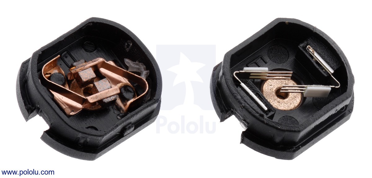
This brings me to another small note about these tiny motors. Most of them don’t have the carbon brushes one begins to expect from the more powerful motors. Mostly they have a strip of copper that’s been stamped to have a few fingers pressing against the commutator. There’s lots of pros to these metal contacts and it’s not all cost cutting, but unless you have managed to read “Electrical Contacts” by Ragnar Holm and actually understood it, they’re hard to explain. There’s all sorts of magic. For example, just forming the right kind of oxide film on the surface of the commutator is a battle all on its own.
It’s a weird trade off. You can make the motor cheaper with the metal contacts, for one. Metal contacts also have much lower friction than carbon or graphite brushes. They’re quieter, and they also transfer less current, which may seem like a bad thing, but if you have a stalled motor with hairlike strands transferring the pixies around the last thing you’d want to do is transfer as much current as possible through them. However, a paper thin sheet of copper is not going to last very long either.
So it comes down to this, at least as I understand it: if bursts of very fast, low energy, high efficiency motion is all that’s required of the motor over its operational life then the metal strip brushes are perfect. If you need to run the motor for a long stretches at a time and noise isn’t an issue then the carbon brush version will work, just don’t stall it. It will cost a little bit more.
Take Care of Your Tiny Motors
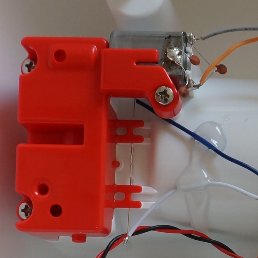
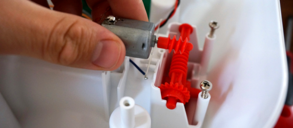
To touch one other small mechanical consideration. They are not designed to take any axial load at all, or really even any radial load either. Most of them have a plastic or aluminum bronze bushing, press-fit into a simple stamped steel body. So if you design a gearbox for one of these be sure to put as little force as possible on the bearing surfaces. If you’ve ever taken apart a small toy you’ve likely noticed that the motor can slide back and forth a bit in its mounting. This is why.
Lastly, because most of these motors are just not intended to run anywhere near their written maximum specifications it is best to assume that their specifications are a well intentioned but complete lie. Most designs work with the bottom 25% of the max number written on the spreadsheet. Running the motor anywhere near the top is usually guaranteed to brick it over time.
These are useful and ubiquitous motors, but unlike their more powerful cousins they have their own set of challenges to work with. However, considering you can buy them by the pound for cheaper than candy, there’s a good reason to get familiar with them.


")