Simple Dev Board Module Socket

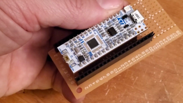
When you’re building a quick prototype or a one-off project it’s nice to be able to securely mount the various modules and development boards. Sometimes these boards have mounting holes, but often they don’t. As an example from the latter category, digital music instrument maker and performer [DIYDSP] shows us how to build a simple socket to mount an STM32 Nucleo-32 module.

The socket is built on a standard pad-per-hole piece of vector board cut to the desired size. Pairs of female pin header strips are soldered down to the board. The inner pair of headers is for the module, the outer pair is for your interconnections. The headers are connected up with short solder bridges, and [DIYDSP] recommends you extend the outer pair several pins longer than necessary. These extras can be used for additional power or ground points, or on some boards they could connect to the debug header pins. He prefers to use female sockets because that lessens the odds that an accidentally bent pin will short something out.

Final step is to drill your mounting holes in the desired location, and no more development boards free-floating and held up only by wires. Do you have any tips for mounting these kinds of modules, either individually as shown here or onto PCBs? Let us know in the comments.

Continue reading “Simple Dev Board Module Socket”

A Modular Mounting System Via 3D Printing

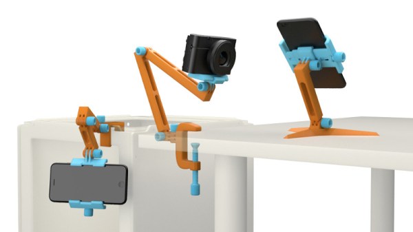
When working with cameras or other tools, it can often be useful to have some manner of stand or tripod to hold things in position, freeing up one’s hands for other tasks. Unfortunately, when it comes to smaller cameras and devices like smartphones and tablets, there are few standardized solutions. [yyh1002] has skirted the problem by creating a customizable modular mounting system, and it’s taken the 3D-printing world by storm.

The system was inspired by GoPro mounts, which are a system of plastic arms and screws that can effectively position the small devices in all manner of orientations. [yyh1002]’s system is GoPro-compatible, using the same fasteners and similar geometry, and tons of other modelers have added on.

The parts are 3D printed and consist of a series of arms, clamps and joints that can be configured to suit the task at hand. Source files are available, which allows custom version to be made. This is useful for modifying parts like phone holders to suit different models, to avoid fouling buttons or interfering with camera placement. Thus far, the community has contributed parts as diverse as G-clamps, camera mounts, and parts to mate to Playstation controllers. (Editor’s note: I’m actually printing out a Pi Zero case from this series as I edit this post. Coincidence!)

It’s a useful system, and we look forward to seeing more parts uploaded in future. Meanwhile, don’t forget – it’s remarkably easy to tripod mount just about anything.

Drill Jig Helps Mount WeMos D1 Mini

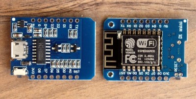
As far as ESP8266 boards go, the WeMos D1 Mini is a great choice if you’re looking to get started with hackerdom’s microcontroller du jour. It’s small, well supported, and can be had ridiculously cheap. Often going for as little as $3 USD each, we buy the things in bulk just to have spares on hand. But that’s not to say it’s a perfect board. For one, it lacks the customary mounting holes which would allow you to better integrate it into finished products.

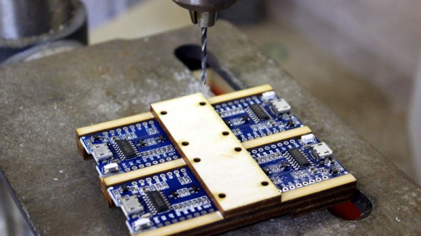
This minor annoyance was enough to spring [Martin Raynsford] into action. He noticed there was some open area on the D1 Mini’s PCB where it seemed he could drill through to add his own mount points, but of course popping holes in a modern PCB can be risky business. There’s not a lot of wiggle room between success and heartbreak, and it’s not like the diminutive D1 Mini is that easy to hold down to begin with. So he designed a laser-cut jig to allow him to rapidly add mounting holes to his D1 Mini’s assembly line style.

For those who might be skeptical, [Martin] reports he’s seen no adverse effects from drilling through the board, though does admit it’s possible the close proximity of the metal screw heads to the ESP8266’s antenna may have a detrimental effect. That said, he’s tested them in his projects out to 25 m (82 feet) with no obvious problems. He’s using a 2 mm drill bit to make his hole, and M2 x 6 mm machine screws to hold the boards down.

The jig design is released as a SVG and DXF for anyone with a laser cutter to replicate, but it shouldn’t be too difficult to extrude those designs in the Z dimension for hackers who haven’t yet jumped on the subtractive manufacturing bandwagon.

When a project makes the leap from prototype to in-house production, designing and building jigs become an essential skill. From flashing firmware to doing final checkout, the time and effort spent building a jig early on will pay for itself quickly in production.

A Mixer (re)built To Travel

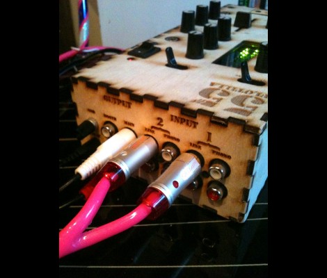
[Toby Cole] likes to mix tunes whenever he gets a chance. But the size of his DJ equipment made it a real bother to lug around with him. He does own a Behringer portable mixer but without cross faders it’s not really all that usable, and most of the other offerings don’t get good reviews. He ended up replacing the enclosure of a proper mixer in order to make it light and small. The growing availability of affordable laser-cut parts made this project possible.

Build Brighton, [Toby’s] local Hackerspace, has a laser cutter. So he knew that if he could figure out a smaller case design it would be a snap to get his parts made. He cracked open the heavy metal case on the KMX 100 mixer and found it had a ton of extra room inside. He designed all of the plates using a digital calipers to properly space the holes and text labels. These designs were combined with BoxMaker to produce the files the laser cutter needed. The first prototype was cut from cardboard, with the finished product cut from 3mm plywood.