Synth Gains Plug And Play Analog MUX

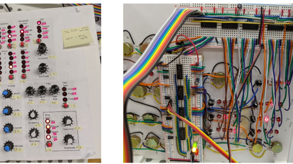
High school computer engineering teacher [Andy Birch] kept losing track of I/O pins on his home-built synth, so he made a custom plug and play addressable MUX system to solve the problem. [Andy]’s synth is based on the Teensy microcontroller, and he was already using CMOS analog 8:1 multiplexer chips (CD4051) to give him more I/O pins. But I/O pin expansion means that now there are more I/O pins to forget. Did I hook up that pitch potentiometer on U3 pin 13 or was it U10 pin 2?

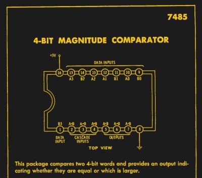
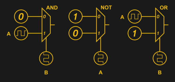
He proceeds to design an addressing system for each I/O card using three bits (expandable to four) supporting eight cards, with a maximum of 16 possible in the future. Since each card may not use all eight signals, each card can tell the Teensy how many signals it has. [Andy] does his address decoding on each card using OR and XOR gates. We would have considered using a single 74HC85 four-bit magnitude comparator instead. That would require only one chip instead of two, but would deprive his students of the opportunity to learn gate level address decoding.

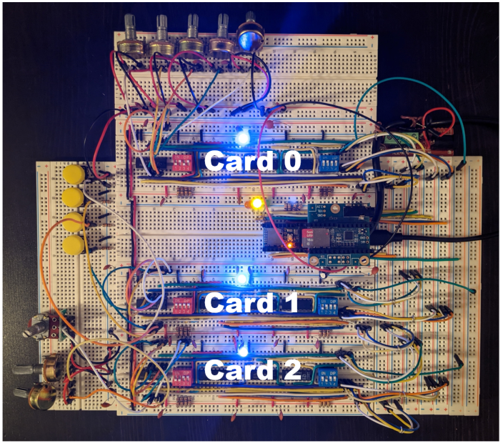
When seeing the term “I/O card”, you may be fooled like we were into thinking this was using PCBs and some kind of motherboard. [Andy]’s I/O cards are actually solderless breadboards mounted on the back of the synth control panel. We really like his bus technique — he removes the power strip sections from several breadboards and repurposes them as address and data buses. Check out the thorough documentation that [Andy] has prepared, and let us know if you have ever designed your own plug and play method for a project in the comments below.

[Ed Note: We love us some muxes!]

I/O Cards — Note the use of Power Strip Bars as Data / Address Buses


Image Sensor From Discrete Parts Delivers Glorious 1-Kilopixel Images

Chances are pretty good that you have at least one digital image sensor somewhere close to you at this moment, likely within arm’s reach. The ubiquity of digital cameras is due to how cheap these sensors have become, and how easy they are to integrate into all sorts of devices. So why in the world would someone want to build an image sensor from discrete parts that’s 12,000 times worse than the average smartphone camera? Because, why not?

[Sean Hodgins] originally started this project as a digital pinhole camera, which is why it was called “digiObscura.” The idea was to build a 32×32 array of photosensors and focus light on it using only a pinhole, but that proved optically difficult as the small aperture greatly reduced the amount of light striking the array. The sensor, though, is where the interesting stuff is. [Sean] soldered 1,024 ALS-PT19 surface-mount phototransistors to the custom PCB along with two 32-bit analog multiplexers. The multiplexers are driven by a microcontroller to select each pixel in turn, one row and one column at a time. It takes a full five seconds to scan the array, so taking a picture hearkens back to the long exposures common in the early days of photography. And sure, it’s only a 1-kilopixel image, but it works.

[Sean] has had this project cooking for a while – in fact, the multiplexers he used for the camera came up as a separate project back in 2018. We’re glad to see that he got the rest built, even with the recycled lens he used. One wonders how a 3D-printed lens would work in front of that sensor.

Continue reading “Image Sensor From Discrete Parts Delivers Glorious 1-Kilopixel Images”

A USB MUXer, For All Your Programming Needs

What if there were something like a KVM switch for your micro programmer, logic analyzer, and other various tools? There was a time when KVM switches (keyboard, video, and mouse, by the way) were metal enclosures surrounding an absurdly complicated rotary switch. This fact has a few applications if you ever want to switch a whole lot of stuff; if you ever need a bazillion-pole, two-way rotary switch, don’t spend your money at Mouser or Digikey, just look at eBay for some really old KVM or parallel port switches. Modern times require modern solutions, so here’s a 16-channel, bi-directional switched bus multiplexer. It connects wires to other wires with USB control, and if you need something like this, you really need something like this.

The SensorDots Port MuxR is a crowdfunding project for a project that began as a programming jig for another project. The MappyDot is a micro LIDAR unit that’s about the size of a postage stamp and has a microcontroller. Obviously, programming those microcontrollers was a pain (and don’t get me started on buying pre-programmed microcontrollers from the manufacturer), but there was a solution: a custom programming rig with dozens of pogo pins that automated the programming of an entire panel of boards. It was a useful tool, and now it’s a good idea for a Kickstarter project.

The Port MuxR takes a set of eight pins, and sends that out to one of eight ports. Alternatively, it can take a set of four pins, and send that to sixteen ports. All of this is controlled via USB, and it works with 0-5V signaling. If you know what this means, you probably have a reason to be interested in it.

Is it a sexy project? No, not at all. It’s an 8-pole, 8-throw rotary switch, controllable over USB. It is interesting, and it’s something a lot of us are going to need eventually.

Relay Computing

Recently, [Manuel] did a post on making logic gates out of anything. He mentioned a site about relay logic. While it is true that you can build logic gates using switch logic (that is, two switches in series are an AND gate and two in parallel are an OR gate), it isn’t the only way. If you are wiring a large circuit, there’s some benefit to having regular modules. A lot of computers based on discrete switching elements worked this way: you had a PCB that contained some number of a basic gate (say, a two input NAND gate) and then the logic was all in how you wired them together. And in this context, the SPDT relay was used as a two input multiplexer (or mux).

In case you think the relay should be relegated to the historical curiosity bin, you should know there are still applications where they are the best tool for the job. If you’re not convinced by normal macroscopic relays, there is some work going on to make microscopic relays in ICs. And even if they don’t use relays to do it, some FPGAs use mux-based logic inside.  So it’s worth your time to dig into the past and see how simply switching between two connections can make a computer.

Mux Mania

How do you go from a two input mux to an arbitrary logic gate? Simple, if you paid attention to the banner image. (Or try it interactive). The mux symbols show the inputs to the left, the output to the right and the select input at the bottom. If the select is zero, the “0” input becomes the output. If the select is one, the “1” input routes to the output.

Continue reading “Relay Computing”