Noise is an annoying but unavoidable part of any engineering project. Fixing noise issues is hard enough, but even just measuring how much noise an amplifier adds to your signal is tricky without proper equipment like a spectrum analyzer. One other thing that makes noise measurements easier is a good, stable noise source that can serve as a reference: you first measure your amplifier without any input, and then measure it again with the noise source connected. Using a few simple formulas you can then calculate how much noise the amplifier produced.
Building a source that generates exactly the amount of noise that you want, no more and no less, is quite a challenge in itself. Several techniques exist, but [Wolfgang] over at the Electronic Projects for Fun blog decided to go for the classic method of using a vacuum diode. He describes the design and analysis of a noise source based on a 2D3B tube in a detailed article.
The tube in question is a special vacuum diode designed to be operated in saturation, meaning at a current high enough to draw away all the electrons generated by the hot filament. When running in this mode, the output current has a noise spectrum that is almost perfectly white, meaning its power level remains constant across the frequency band. [Wolfgang]’s measurements show a deviation of no more than 0.2 dB between 200 kHz and 200 MHz. This is about as close to perfect as you can get, and covers most of the frequency bands of interest to radio amateurs.
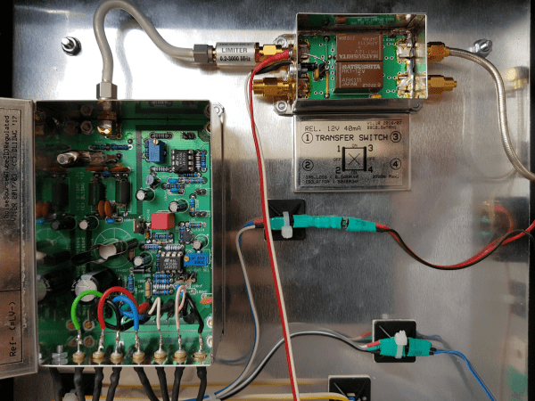
The whole project is built up inside a sturdy metal box, with extensive shielding and line filtering to keep undesired signals from contaminating the clean noise signal. A limiter is also an essential component: should the diode’s filament break, the limiter will prevent the sudden transient from reaching the spectrum analyzer and destroying its (very expensive) input stage.
[Wolfgang] has made a few other noise sources based on various components, which he compares on a separate page, although the 2D3B based one is by far the most stable. We’ve also featured a simple pink noise source, which is useful for audio measurement, as well as white noise sources designed to generate random numbers or simply to help you sleep.