Still Up And Coming: Non-Planar FDM 3D Printing With 3 Or 6 Axes

Printing the non-planar PLA part on top of the non-planar side of the PETG part. (Credit: Michael Wüthrich)

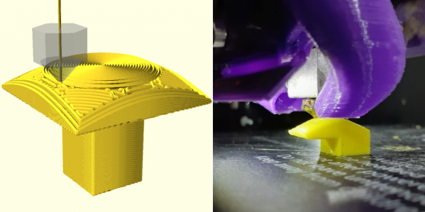
Most of the time FDM 3D printing involves laying down layers of thermoplastics, but the layer lines also form the biggest weakness with parts produced this way. Being able to lay out the lines to follow the part’s contours can theoretically strengthen the part and save material in the process. Recently, [Michael Wüthrich] demonstrated an approach that uses a modified Prusa Mini FDM printer to first lay out a part in PETG using non-planar printing, after which this PETG part was used to print on top of in PLA, effectively using the PETG as a ‘printbed’ from which the PLA can be easily removed and leaving the PLA part as fully non-planar on both sides.

The modification to the Prusa Mini printer is covered on Printables along with the required parts. The main change is to give the nozzle as much clearance as possible, for which [Michael] uses the E3D Revo belt nozzle. This nozzle requires a custom holder for the Prusa Mini. After this the printer is ready for non-planar printing, but as [Michael] notes in the Twitter thread, he did not use a slicer for this, as none exists. Instead he used Matlab, a custom script and a lot of manual labor.

Continue reading “Still Up And Coming: Non-Planar FDM 3D Printing With 3 Or 6 Axes”

3D Printing 90° Overhangs With Non-Planar Slicing

When slicing a model for 3D printing, the part is divided into a stack of flat, 2D layers. But there’s an alternative in the form of non-planar slicing, where the layers can follow 3D curves. [Rene K. Mueller] took this a step further and successfully used non-planar slicing to print 90° overhangs on a normal Cartesian FDM printer.

Non-planar layers have been around for a while, but were generally limited to creating smooth curves without layer lines. The idea of using the technique for overhangs had been floating around in [Rene]’s head for a while, and he was spurred to action after seeing the rotating tilted nozzle printer featured here on Hackaday. The idea is only to have the outer edge of each layer overhang, by making each layer slope downward toward the overhang. [Rene] programmed a conic slicer algorithm for this purpose, which splits the model into dome-shaped layers, like an onion.

He did a lot of testing and documented the results in detail. Conical slices were compared with tilted slices, which are also used for belt 3D printers. Both have some geometric limitations. Tilted slices can only print the overhang in one direction, but conical slices can do this in all directions, allowing it to create a mushroom-like shape without any support. The limitation is that it can only print inward or outward from a central point. More complex geometry must be segmented, and each sub-volume sliced separately. The slicing angle is also limited by the shape of the print head, to avoid it crashing into the print.

We think this technique has a lot of potential for widespread use, especially since it is compatible with most existing FDM printers. It is still a work in progress, but support has already been added for Slic3r and Prusa Slicer. We look forward to seeing how it develops and gets adopted.

3D Printering: Non-Planar Layer FDM

Non-planar layer Fused Deposition Modeling (FDM) is any form of fused deposition modeling where the 3D printed layers aren’t flat or of uniform thickness. For example, if you’re using mesh bed leveling on your 3D printer, you are already using non-planar layer FDM. But why stop at compensating for curved build plates? Non-planar layer FDM has more applications and there are quite a few projects out there exploring the possibilities. In this article, we are going to have a look at what the trick yields for us.

Continue reading “3D Printering: Non-Planar Layer FDM”