We’ve all heard of the dangers of static electricity when dealing with electronics, and we all take the proper precautions when working with static-sensitive components — don’t we? But as much as we fear punching an expensive hole in a chip with an errant spark, electrostatic discharge damage isn’t the only kind of static hazard your digital designs can face.
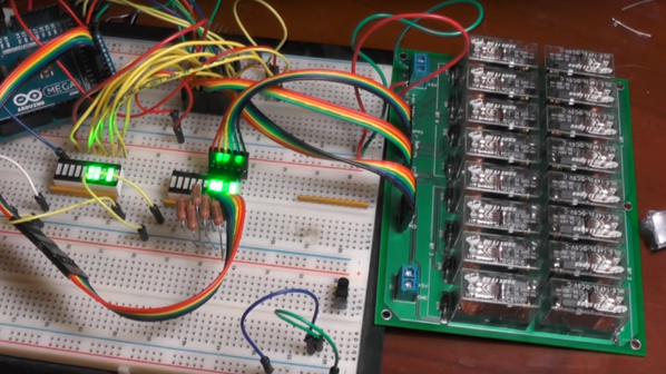
To be fair, the static hazard demonstrated by [Shane Oberloier] in the video below isn’t really an electrostatic problem. “Static” in this case refers to when a change to an input of a logic circuit gives an unexpected output until the circuit stabilizes. The circuit shown is pretty simple, with three inputs going into a combination of AND and NOT gates before going into an OR gate. The static hazard manifests as a glitch in the output when the middle input line’s logical state is toggled; according to the circuit’s truth table, the output shouldn’t change under these conditions, but the oscilloscope clearly captures a high-low-high blip. [Dr. Shane]’s explanation of why this happens makes perfect sense: the inverter on that input line has a brief but non-zero propagation time, putting the whole circuit in an ambiguous state before finally settling down to the correct output value.
So how do you fix something like this? This gets into the Boolean weeds a bit, and we won’t pretend to fully understand it, but at least for this case, [Dr. Shane] was able to add a single AND gate to sum the two other inputs and pipe the output into another input of the OR gate. That has the effect of canceling out the race condition caused by the inverter, but at the expense of a more complicated circuit, of course.
We found this to be a fascinating and informative discussion of a potential pitfall in logic design. But, if you still want to see some MOSFETs executed with static electricity, who are we to object?
Continue reading “The Other Kind Of Static Hazard To Your Logic Circuits”


