The Kraakdoos — Musical Abuser Of An Ancient OpAmp

A friend from the newly founded Yeovil Hackerspace introduced me to a device known as “The Kraakdoos” or cracklebox.

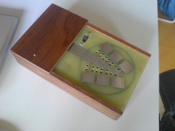
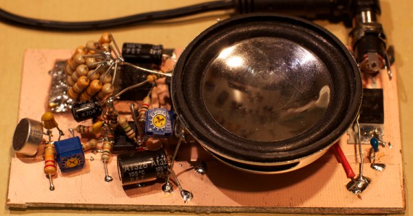
The cracklebox is an early electronic instrument produced by STEIM in the 1970s. The instrument consists of a single PCB with a number of copper pads exposed on one side. The player touches the pads and the instrument emits… sounds which can perhaps best be described as squeeze and squeals.

While the cracklebox was original sold as a complete instrument, the device has been reverse engineered, and the schematic documented. What lies inside is quite fascinating.

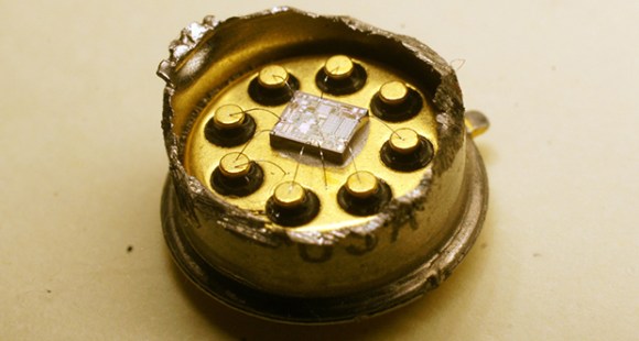
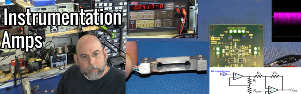
The heart of the cracklebox is an ancient opamp, the LM709. The LM709 is the predecessor to the famous LM741. Unlike the 741 the 709 had no internal frequency compensation. Frequency compensation is used to intentionally limit the bandwidth of an opamp. As input frequency increases, the phase shift of the opamp also increases. This can result in undesirable oscillation, as the feedback network forms an unintentional phase-shift oscillator.

Most modern opamps have internal frequency compensation, but the 709 doesn’t. Let’s see how this is used in the cracklebox:

krackdoos_sch
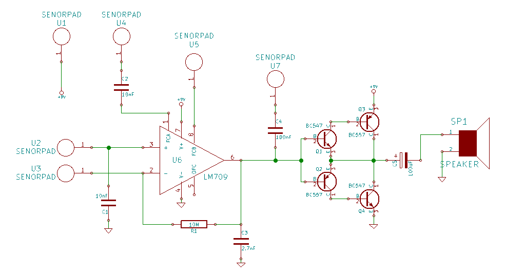
Rather than using the frequency compensation pins as intended the cracklebox just routes them out to pads. In fact the cracklebox routes almost all the pins on the opamp out to pads, including the inverting and non-inverting inputs. A single 1MOhm feedback resistor is used in a non-inverting configuration. However reports suggest the instrument can work without a feedback resistor at all!

Continue reading “The Kraakdoos — Musical Abuser Of An Ancient OpAmp”

Instrumentation Amplifiers with Bil Herd

Instrumentation Amplifiers And How To Measure Miniscule Change

These days there a large number of sensors and analog circuits that are “controller friendly” meaning that their output signal is easily interfaced to the built-in Analog to Digital Convertors (ADCs) often found in today’s micro-controllers. This means that the signals typically are already amplified, often filtered, and corrected for offset and linearity. But when faced with very low level signals, or signals buried in a larger signal an Instrumentation Amplifier may be what’s needed. The qualities of an Instrumentation Amplifier include:

  • A differential amplifier with high impedance and low bias current on both inputs.
  • Low noise and low drift when amplifying very small signals.
  • The ability to reject a voltage that is present on both inputs, referred to as Common Mode Rejection Ratio (CMRR)

Continue reading “Instrumentation Amplifiers And How To Measure Miniscule Change”

hassler_pcb

Annoy Your Enemies With The Hassler Circuit

[Craig] recently built himself a version of the “hassler” circuit as a sort of homage to Bob Widlar. If you haven’t heard of Bob Widlar, he was a key person involved in making analog IC’s a reality. We’ve actually covered the topic in-depth in the past. The hassler circuit is a simple but ingenious office prank. The idea is that the circuit emits a very high frequency tone, but only when the noise level in the room reaches a certain threshold. If your coworkers become too noisy, they will suddenly notice a ringing in their ears. When they stop talking to identify the source, the noise goes away. The desired result is to get your coworkers to shut the hell up.

[Craig] couldn’t find any published schematics for the original circuit, but he managed to build his own version with discrete components and IC’s. Sound first enters the circuit via a small electret microphone. The signal is then amplified, half-wave rectified, and run through a low pass filter. The gain from the microphone is configurable via a trim pot. A capacitor converts the output into a flat DC voltage.

The signal then gets passed to a relaxation oscillator circuit. This circuit creates a signal whose output duty cycle is dependent on the input voltage. The higher the input voltage, the longer the duty cycle, and the lower the frequency. The resulting signal is sent to a small speaker for output. The speaker is also controlled by a Schmitt trigger. This prevents the speaker from being powered until the voltage reaches a certain threshold, thus saving energy. The whole circuit is soldered together dead bug style and mounted to a copper clad board.

When the room is quiet, the input voltage is low. The output frequency is high enough that it is out of the range of human hearing. As the room slowly gets louder, the voltage increases and the output frequency lowers. Eventually it reaches the outer limits of human hearing and people in the room take notice. The video below walks step by step through the circuit. Continue reading “Annoy Your Enemies With The Hassler Circuit”

Demodulating BPSK31 With OpAmps And 555s

BPSK31 is an extremely popular mode for amateur radio operators; it’s efficient and has a narrow bandwidth and can be implemented with a computer sound card or an Arduino. Just like it says on the tin, it’s phase shift keying, and a proper implementation uses a phase detection circuit or something similar. [Craig] thought it would be fun to build an analog BPSK31 demodulator and hit upon the idea of doing this with amplitude demodulation. No, this isn’t the way you’re supposed to do it, but it works.

Data is transmitted via BPSK31 with a phase shift of 180 degrees being a binary 0, and no phase shift being a binary 1. [Craig]’s circuit uses an op-amp and a pair of diodes to do a full wave rectification of the signal, which basically makes a binary 1 logic high, and binary 0 logic low.

This rectified signal is then fed into a comparator, making the output go high when the signal is above 2V, and low when the signal is below 1V. That’s all you need to do to get bits out of the signal, all [Craig] had to do after that was figure out a way to sample it.

A 555 set up in astable mode running at 31.25 Hz provides the clock, synchronized with the signal by connecting the comparator’s output to the 555 trigger input. The timer clock ends up being slightly slower, but thanks to the varicode character set, the maximum number of binary ones the circuit will see is nine; every time the trigger sees a zero, the timer’s trigger is reset, re-synchronizing the receiver’s clock.

Yes, it’s a hack, and no, this isn’t how you’re supposed to receive PSK. It does, however, work, and you can thank [Craig] for that.

board

The Disintegrated Op Amp

741
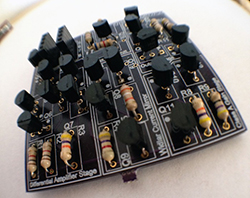
By now we’ve all seen the ‘Three Fives’ kit from Evil Mad Scientist, a very large clone of the 555 timer built from individual transistors and resistors. You can do a lot more in the analog world with discrete parts, and [Shane]’s SevenFortyFun is no exception: it’s a kit with a board, transistors, and resistors making a very large clone of the classic 741 op-amp, with all the parts laid bard instead of encapsulated in a brick of plastic.

[Shane] was inspired by the analog greats – [Bob Pease], [Jim Williams], and of course [Bob Widlar], and short of mowing his lawn with goats, the easiest way to get a feel for analog design was to build some analog circuits out of individual components.

[Shane] has a few more kits in mind: a linear dropout and switching regulators are on the top of the list, as is something like the Three Fives kit, likely to be used to blink giant LEDs.

Fake Audiophile Opamps Revealed

chip

The OPA627 is an old, popular, and very high-end opamp found in gear cherished by the most discerning audiophiles. This chip usually sells for at least $15, but when [Zeptobars] found a few of these expensive chips on ebay going for $2, his curiosity was piqued. Something just isn’t right here.

[Zeptobars] is well known for his decapsulating and high-resolution photography skills, so he cut the can off a real OPA627, and dissolved one of the improbably cheap ebay chips to reveal the die. Under the microscope, he found an amazing piece of engineering in the real chip – laser trimmed resistors, and even a nice bit of die art.

The ebay chip, if it were real, would look the same. It did not. The ebay chip only contained one laser trimmed resistor and looks to be a much simpler circuit. After a bit of research, [Zeptobars] found it was actually an AD774 opamp. The difference is small, but the AD774 still has much higher noise – something audiophiles could easily differentiate with their $300 oxygen-free volume knobs.

This isn’t the first instance of component counterfeiting [Zeptobars] has come across. He’s found fake FTDI chips before, and we’re counting the days until he gets around to putting a few obviously fake ebay 6581 SID chips under the microscope.

A Mini Op-Amp Based Line Following Robot

LineRobot

There’s no denying it. Super small robots are just cool. [Pinomelean] has posted an Instructable on how to create a mini line following robot using only analog circuitry. This would make a great demo project to show your friends and family what you’ve been up to.

Analog circuitry can be used instead of a microcontroller for many different applications, and this is one of them. The circuit consists of two op-amps that amplify the output of two phototransistors, which control each motor. This circuit is super simple yet very effective. The mechanical system is also quite cool and well thought out. To keep things simple, the motors drive the wheel treads, rather than directly through an axle. After the build was completed, the device needed to be calibrated by turning potentiometers that control the gain of each op-amp. Once everything is balanced, the robot runs great! See it in action after the break.

While not the smallest line follower we have seen, this robot is quite easy to reproduce. What little robots have you build lately? Send us a tip and let us know!

[via Embedded Lab]

Continue reading “A Mini Op-Amp Based Line Following Robot”