Stepping Through Code On A Pace 4000 Set Top Box

[Lee] wrote in to tell us about a Set Top Box he hacked. Before the cable industry lawyers get out their flaming swords… he’s not stealing cable, or really doing much of anything. This is a hack just for the adventure and thrill of making someone else’s hardware design do your bidding without any kind of instructions.

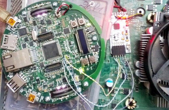
He posted about the adventure in two parts. The first is finding the JTAG header and identifying the pins. Arduino to the rescue! No really, and this is the type of Arduino use we love. Using a package called JTAGenum the board becomes a quick tool for probing and identifying JTAG connections.

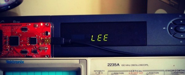
The image above shows a different piece of hardware. From looking at it we’re pretty sure this is a Bus Blaster which is specifically designed for JTAG debugging with ARM processors. This is the beginning of the second part of his documentation which involves code dumping and stepping through lines code (or instructions) using OpenOCD and GDB. It’s a chore to follow all that [Lee] discovered just to write his name to the display of the box. But we certainly found it interesting. The display has a convoluted addressing scheme. We assume that there are cascading shift registers driving the segments and that’s why it behaves the way it does. Take a look for yourself and let us know what you think in the comments.

Stealing WiFi From LED Lightbulbs

LIFX Wireless LED PCB

Back in 2012, the LIFX light bulb launched on Kickstarter, and was quite successful. This wireless LED lightbulb uses a combination of WiFi and 6LoWPAN to create a network of lightbulbs within your house. Context Information Security took a look into these devices, and found some security issues.

The LIFX system has a master bulb. This is the only bulb which connects to WiFi, and it sends all commands out to the remaining bulbs over 6LoWPAN. To keep the network up, any bulb can become a master if required. This means the WiFi credentials need to be shared between all the bulbs.

Looking into the protocol, an encrypted binary blob containing WiFi credentials was found. This binary could easily be recovered using an AVR Raven evaluation kit, but was not readable since it was encrypted.

After cracking a bulb apart, they found JTAG headers on the main board. A BusBlaster and OpenOCD were used to communicate with the chip. This allowed the firmware to be dumped.

Using IDA Pro, they determined that AES was being used to encrypt the WiFi credentials. With a bit more work, the key and initialization vector was extracted. With this information, WiFi credentials sent over the air could be decrypted.

The good news is that LIFX fixed this issue. Now they generate an encryption key based on WiFi credentials, preventing a globally unique key from being used.

[via reddit]

Evalbot As A JTAG Programmer

evalbot-as-jtag-programmer

[Adarsh] needed a JTAG programmer to push code to a CPLD dev board he was working with. He knew he didn’t have a dedicated programmer but figured he could come up with something. Pictured above is his hack to use a Stellaris Evalbot as a programmer.

Long time readers will remember the Evalbot coupon code debacle of 2010. The kits were being offered with a $125 discount as part of a conference. We were tipped off about the code not know its restrictions, and the rest is history. We figure there’s a number of readers who have one collecting dust (except for people like [Adam] that used it as a webserver). Here’s your chance to pull it out again and have some fun.

A bit of soldering to test points on the board is all it takes. The connections are made on the J4 footprint which is an unpopulated ICDI header. On the software side [Adarsh] used OpenOCD with stock configuration and board files (specifics in his writeup) to connect to the white CPLD board using JTAG.

How To Build OpenOCD With Stellaris Launchpad Support

The stable version of OpenOCD (an open source On-Chip Debugging software package) doesn’t have support for the ICDI protocol used by the Stellaris Launchpad board. But it is pretty easy to build your own OpenOCD from source after patching it to use the protocol.

We’ve already seen an open source tool used to flash binary images to the TI ARM board. But that can’t be used with GDB. With the recent inclusion of USB-based ICDI in the OpenOCD development branches we gain all the features that come with the package. We’re quite happy hear about this as we use OpenOCD for many hardware architectures and this makes development for this board feel more like normal.

Our Stellaris Launchpad hasn’t just been sitting in the closet since we got it. We’ve learned a lot by using the lm4tools to program the chip as we work our way through the online workshop. We’re really beginning to like the Stellarisware peripheral library that has been provided. For us it works in a much more intuitive way than the one that STM uses with their ARM Discovery boards. We’d recommend taking a look at the workbook PDF (which is basically a verbose listing of what’s in the video series) and the library reference (called SW-DRL-UG-9453.pdf) which is in the docs folder of the Stellarisware package.

[via Dangerous Protoypes]

STM32 F4 Discovery Tutorial Using Open Source Tools

[Pulko Mandy] got his hands on the new STM32 F3 Discovery board. He’s a fan of the open source tools just like we are, so he posted a guide covering the use of an open source toolchain with the F3 hardware.

This board was just announced earlier this month but there is already support for it in OpenOCD. It’s not all that different from the F4 board, which we would think made the process a bit easier. [Pulko] is using the Sourcery CodeBench Lite toolchain, which works for pretty much all of the ARM chips out there. It is GCC based and comes with GDB for debugging (along with all the other tools you would expect). He did created his own Linker script and startup code. These are crucial for ARM so it’s nice that he provided them for us. He finishes up the guide by showing how OpenOCD can be used to flash the code to the chip and how it works with the debugger.

[Photo source]

Beginner’s Look At On-Chip Debugging

As your embedded applications get more complicated an On-Chip Debugger will save you a lot of time when things don’t run quite right. On-Chip Debugging (OCD) is just what it sounds like — a way to run your program on the target chip that lets you pause execution to examine values and change them if need be. The Arduino has no built-in method of using OCD, but the AVR chips used by the boards do. The caveat is that you need a proper AVR programmer to access the Debug Wire protocol, or a JTAG interface for some of the larger chips. In this case I’m going to be using an STM32 Discovery Board to give you an overview of OCD. But this will work the same way for any chip that has hardware debugging capabilities. Many IDE’s have debugging support built right in so that you can use a nice GUI as you work. But often these are just a front end for the command line tools I’ll be using. Join me after the break and we’ll get started.

Continue reading “Beginner’s Look At On-Chip Debugging”

Template For Building STM32F0-Discovery Project In GCC

Yep, that blue light is blinking and I made it happen. I’ve been hard at work since I got my free STM32F0-Discovery board in the mail. Most recently I put together a starting template for building STM32F05x project on Linux. You’ll still need to install your own tool chain (I’m using the Code Sourcery G++: Lite Edition), but this makes it a snap to compile your projects with support for STM’s peripheral libraries.

As for programming, you may remember that I added support for writing to RAM in the stlink project. I’ve wasted spent a ton of time trying to get support for writing to Flash into that project. It’s just less of a hassle to use stlink than it is to work with OpenOCD. But I’ve really hit a wall getting the flash loader code to work. If you want to check out what I’ve done so far in that area I committed a very messy branch (see the commits for what code changes I’ve made).

In the mean time you can use OpenOCD to write images compiled with the template to your device. I included the ‘make program’ option in the Makefile to do this from command line. If you need help compiling OpenOCD check the readme in the template repository.