When it comes to our analog designs, op-amps tend to be just another jellybean part. We tend to spec whatever does the job, and don’t give much of a thought as to the internals. And while it doesn’t make much sense to roll your own op-amp out of discrete components, that doesn’t mean there isn’t plenty to be learned from doing just that.
While we’re more accustomed to seeing [Mitsuru Yamada]’s digital projects, he’s no stranger to the analog world. In fact, this project is a follow-on to his previous bipolar transistor op-amp, which we featured back in 2021. This design features MOSFETs rather than BJTs, but retains the same basic five-transistor topology as the previous work, with a differential pair input stage, a gain stage, and a buffer stage. Even the construction of the module is similar, using his trademark perfboard and ultra-tidy wiring.
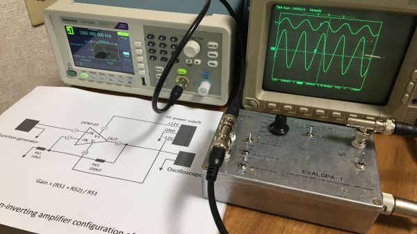
Also new is a flexible evaluation unit for these discrete op-amp modules. This very sturdy-looking circuit provides an easy way to configure the op-amp for testing in inverting, non-inverting, and transimpedance mode, selecting from a range of feedback resistors, and even provides a photodiode input. The video below shows the eval unit in action with the CMOS module, as well as highlights the excellent construction [Mitsuru Yamada] is known for.
Looking for some digital goodness? Check out the PERSEUS-8, a 6502 machine we wish had been a real product back in the day.
Hurricane season is rapidly approaching those of us who live in the northern hemisphere. While that does come with a good deal of stress for any homeowners who live in the potential paths of storms it also comes with some opportunities for treasure hunting. Storms tend to wash up all kinds of things from the sea, and if you are equipped with this DIY metal detector you could be unearthing all kinds of interesting tchotchkes from the depths this year.
The metal detector comes to us from [mircemk] who is known for building simple yet effective metal detectors. Unlike his previous builds, this one uses only a single integrated circuit, the TL804 operational amplifier. It also works on the principle of beat-balance which is an amalgamation of two unique methods of detecting metal. When the wire coils detect a piece of metal in the ground, the information is fed to an earpiece through an audio jack which rounds out this straightforward build.
[mircemk] reports that this metal detector can detect small objects like coins up to 15 cm deep, and larger metal objects up to 50 cm. Of course, to build this you will also need the support components, wire, and time to tune the circuit. All things considered, though it’s a great entryway into the hobby.
Circuit simulations are great because you can experiment with circuits and make changes with almost no effort. In Circuit VR, we look at circuits using a simulator to do experiments without having to heat up a soldering iron or turn on a bench supply. This time, we are going to take a bite of a big topic: op amps.
The op amp — short for operational amplifier — is a packaged differential amplifier. The ideal op amp — which we can’t get — has infinite gain and infinite input impedance. While we can’t get that in real life, modern devices are good enough that we can pretend like it is true most of the time.
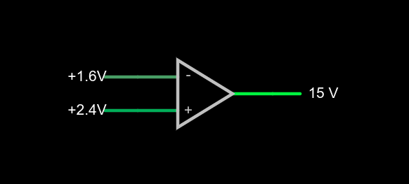
a very simple op amp circuit with some detail omitted
If you open this circuit in the Falstad simulator, you’ll see two sliders to the right where you can tweak the input voltage. If you make the voltages the same, the output will be zero volts. You might think that a difference amplifier would take inputs of 1.6V and 2.4V and either produce 0.8V or -0.8V, but that’s not true. Try it. Depending on which input you set to 2.4V, you’ll get either 15V or -15V on the output. That’s the infinite gain. Any positive or negative output voltage will quickly “hit the rail” or the supply voltage which, in this case, is +/-15V.
Practical Concerns
The biggest omitted detail in the schematic symbol above is that there’s no power supply here, but you can guess that it is +/- 15V. Op amps usually have two supplies, a positive and a negative and while they don’t have to be the same magnitude, they often are. Some op amps are specifically made to work with a single-ended supply so their negative supply can connect to ground. Of course, that presupposes that you don’t need a negative voltage output.
The amount of time it takes the output to switch is the slew rate and you’ll usually find this number on the device datasheet. Obviously, for high-speed applications, a fast slew rate is important, particularly if you want to use the circuit as a comparator as we are here.
Other practical problems arise because the op amp isn’t really perfect. A real op amp would not hit the 15V rail exactly. It will get close depending on how much current you draw from the output. The higher the current, the further away from the rails you get. Op amps will also have some offset that will prevent it from hitting zero when the inputs are equal, although on modern devices that can be very low. Some older devices or those used in high-precision designs will have a terminal to allow you to trim the zero point exactly using an external resistor.
Op Amps Can Provide Steady Voltage Under Variable Load
Rather than dig through a lot of math, you can deal with nearly all op amp circuits if you remember two simple rules:
The inputs of the op amp don’t connect to anything internally.
The output mysteriously will do what it can to make the inputs equal, as far as it is physically possible.
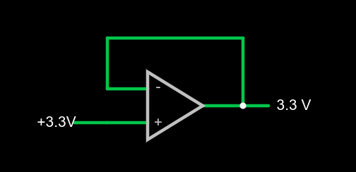
1x amplifier
That second rule will make more sense in a minute, but we already see it in action. Set the simulator so the – input (the inverting input) is at 0V and the noninverting input (+) is at 4V. The output should be 15V. The output is trying to make the inverting input match the noninverting one, but it can’t because there is no connection. The output would like to provide an infinite amount of voltage, but it can only go up to the rail which is 15V.
We can exploit this to make a pretty good x1 amplifier by simply shorting the output to the – terminal. Remember, our rules say the input terminals appear to not connect to anything, so it can’t hurt. Now the amplifier will output whatever voltage we put into it:
You might wonder why this would be interesting. Well, we will learn how to increase the gain, but you actually see this circuit often enough because the input impedance is very high (infinite in theory, but not practice). And the output impedance is very low which means you can draw more current without disturbing the output voltage much.
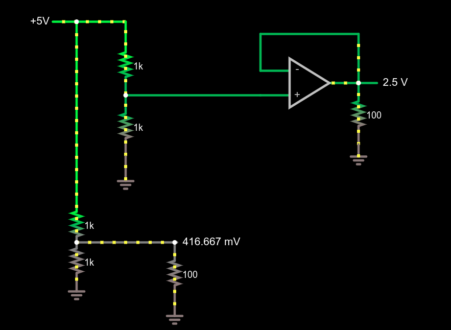
Comparing voltage divider performance with and without a 1x amplifier
This circuit demonstrates the power of a 1x amplifier. Both voltage dividers produce 2.5V with no load. However, with a 100 ohm load at the output, the voltage divider can only provide around 400mV. You’d have to account for the loading in the voltage divider design and if the load was variable, it wouldn’t be possible to pick a single resistor that worked in all cases. However, the top divider feeds the high impedance input of the op amp which then provides a “stiff” 2.5V to whatever load you provide. As an example, try changing the load resistors from 100 ohms to different values. The bottom load voltage will swing wildly, but the top one will stay at 2.5V.
Don’t forget there are practical limits that won’t hold up in real life. For example, you could set the load resistance to 0.1 ohms. The simulator will dutifully show the op amp sourcing 25A of current through the load. Your garden-variety op amp won’t be able to do that, nor are you likely to have the power supply to support it if it did.
What’s Being Amplified?
This is an amplifier even though the voltage stayed the same. You are amplifying current and, thus, power. Disconnect the bottom voltage divider (just delete the long wire) and you’ll see that the 5V supply is providing 12.5 mW of power. The output power is 62.5 mW and, of course, varies with the load resistor.
Notice how this circuit fits the second rule, though. When the input changes, the op amp makes its output equal because that’s what makes the + and – terminals stay at the same voltage.
Of course, we usually want a higher voltage when we amplify. We can do that by building a voltage divider in the feedback loop. If we put a 1:2 voltage divider in the loop, the output will have to double to match the input and, as long as that’s physically possible, that’s what it will do. Obviously, if you put in 12V it won’t be able to produce 24V on a 15V supply, so be reasonable.
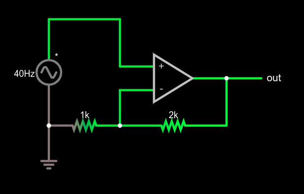
Non-inverting amplifier example
This type of configuration is called a non-inverting amplifier because, unlike an inverting amplifier, an increase in the input voltage causes an increase in the output voltage and a decrease in input causes the output to follow.
Note that the feedback voltage divider isn’t drawn like a divider, but that’s just moving symbols on paper. It is still a voltage divider just like in the earlier example. Can you figure the voltage gain of the stage? The voltage divider ratio is 1:3 and, sure enough, a 5V peak on input turns into a 15V peak on the output, so the gain is 3. Try changing the divider to different ratios.
What’s Next?
While it isn’t mathematically rigorous, thinking of the op amp as a machine that makes its inputs equal is surprisingly effective. It certainly made the analysis of these simple circuits, the comparator, the buffer amplifier, and a general non-inverting amplifier simple.
There are, of course, many other types of amplifiers, as well as other reasons to use op amps such as oscillators, filters, and other even more exotic circuits. We’ll talk about some of them next time and the idea of a virtual ground, which is another helpful analysis rule of thumb.
[Jack] tipped us about a Crossed Bananas Display (CBD) he just designed. A CBD is a tuning aid for frequency-shift keyed (FSK) modes and is basically an oscilloscope in X-Y mode. At one time, radioteletype operators used binary FSK to transmit text over radio waves. In this scheme, the “1” is called the mark frequency and the “0” is called the space frequency. If both frequencies were perfectly tuned (correct phase) the resulting display would look like the one shown above, explaining the origin of the “crossed banana” name.
The build is based on an ATmega328 and a 1.8″ ST7735R display which has a 128×160 resolution. The MC33204PG operational amplifier is used in conjunction with a potentiometer to scale the input in the microcontroller ADC’s range. Another potentiometer sets the refresh rate of the graph. The whole project is enclosed in a painted cast-aluminium bud box and all the sources for this project can be found here.
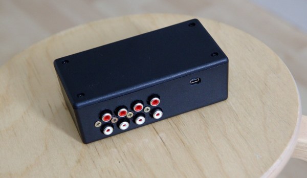
As [Jan-Erik] had already built a simple USB connected Digital-to-Analog Converter (DAC), he decided to make the high-end version of it.
The prototype you see in the picture above is based on:
the PCM2707C from Texas Instruments which takes care of the USB communication and outputs I2S audio data
the PCM1794A, a 132dB SNR 24-bit 192kHz DAC which receives I2S protocol
the OPA4134, a high performance audio operational amplifier
The on-board +3.3V and -5V voltages are generated by inductor-less power supplies. As [Jan-Erik] mentions in his write-up, the ‘high-end’ was put between single quotes because the PCB is single sided and uses through hole passive components. The board was designed using Kicad, etched by himself and put in a machined enclosure. All the production files can be downloaded from his website so you may produce it within a day.