A Transistor-less Sound Synthesizer

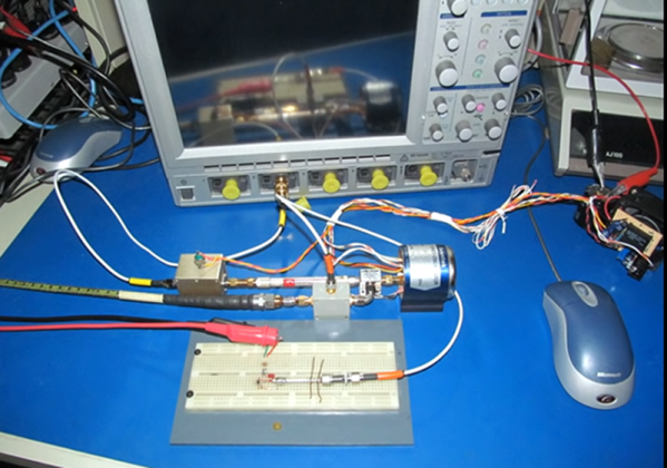
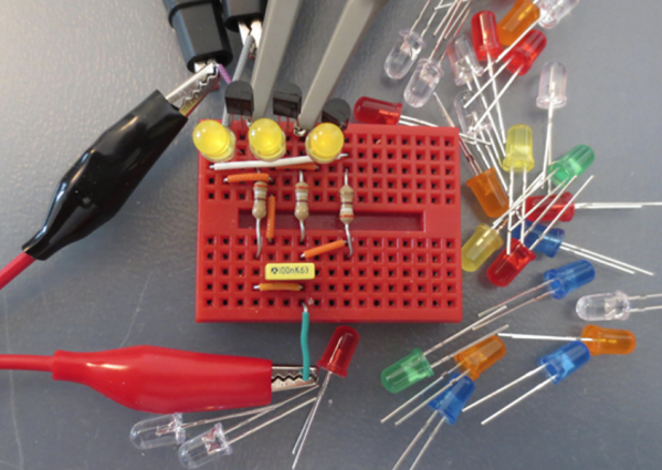
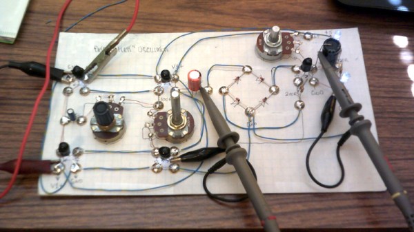
A synthesizer without transistors could almost be the basis of a trick question, surely without transistors it must be using a vacuum tube or similar. Not [Dr. Cockroach]’s synth though, instead of transistors it uses coupled pairs of LEDs and light-dependent resistors as its active components. Its oscillator circuit comes courtesy of [Patrick Flett], and uses a pair of LED/LDR combinations to alternately charge and discharge a capacitor. This feeds another LDR/LED pair that appears to act as a buffer to drive a bridge rectifier, with a final amplifier following it.

The result oscillates, though at frequencies in the low audio range with a cluster of harmonics thrown in. Its sound is best described as something akin to a small single-cylinder motorcycle engine at the lower frequencies, and is something we see could have all sorts of interesting possibilities.

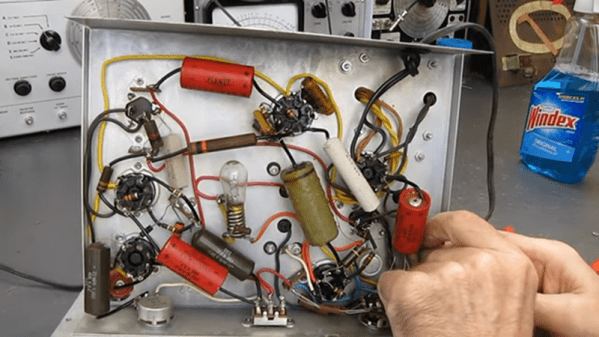
This approach of using LDR-based active devices may be something of a dead end that could have had its day back in the 1930s, but it’s nevertheless an entertaining field to explore. It’s not the first time we’ve followed [Dr. Cockroach] at it, in the past we’ve seen the same technique applied to logic gates.

Have a listen to the synth in the video below the break. Continue reading “A Transistor-less Sound Synthesizer”

Breadboard Breaks The Speed Barrier

It is common wisdom that solderless breadboards are only good for low frequencies. But how fast can they really go? There’s been a contest going on to see who can make the fastest breadboard-mounted oscillator and [Joe Smith] has been trying to keep his leading position. He’s already managed 6 GHz and now he’s shooting for 20 GHz, as you can see in the video below.

One of the biggest challenges at these frequencies is just measuring your output. You may have a scope, but how does it do at 20 GHz? So half of the story is how [Joe] managed to monitor his output.

Continue reading “Breadboard Breaks The Speed Barrier”

Eico Signal Generator Gets A Repair

The Eico model 377 was a pretty common audio signal generator. [The Radio Mechanic] picked one up from 1956 that was in reasonably good shape, and shares a teardown and repair of the unit that you can see in the video below. The device could produce sine and square waves using a few tubes.

The unit was a bit different inside than expected because there were several versions made that shared the same model number. The bottom of the case had some goo in it, which is never a good sign. Unsurprisingly, the culprit was an old capacitor.

Continue reading “Eico Signal Generator Gets A Repair”

Chaotic Oscillator From Antique Logic

While working on recreating an “ancient” (read: 60-year-old) logic circuit type known as resistor-transistor logic, [Tim] stumbled across a circuit with an unexpected oscillation. The oscillation appeared to be random and had a wide range of frequency values. Not one to miss out on a serendipitous moment, he realized that the circuit he built could be used as a chaotic oscillator.

Chaotic systems can be used for, among other things, random number generation, so making sure that they do not repeat in a reliable way is a valuable property of a circuit. [Tim]’s design uses LEDs in series with the base of each of three transistors, with the output of each transistor feeding into the input of the next transistor in line, forming a ring. At certain voltages close to the switching voltages of the transistors, the behavior of the circuit changes unpredictably both in magnitude and frequency.

Building real-life systems that exhibit true randomness or chaotic behavior are surprisingly rare, and even things which seem random are often not random enough for certain applications. [Tim]’s design benefits from being relatively simple and inexpensive for how chaotic it behaves, and if you want to see his detailed analysis of the circuit be sure to visit his project’s page.

If you want to get your chaos the old fashioned way, with a Chua circuit, look out for counterfeit multipliers.

This PIC Is A Squarewave Generator

When we use a microcontroller to flip a few GPIOs or talk SPI to a peripheral chip, we are often overlooking that it will usually contain an array of built-in peripherals that were once the preserve of extra hardware. Analogue ports, timers, UARTs, and clock generators, to name just a few. [Giovanni Bernardo] has been experimenting with one of these, the internal frequency synthesiser on many PIC microcontrollers, and he’s  produced a handy square wave generator for which he’s placed code on GitHub and produced a write-up (Italian language, Google translate link).

The board used is a PIC16F375 Curiosity Nano, and code takes input from a rotary encoder to set the frequency, with a button to select different step sizes and an alphanumeric LCD display to show the current settings. Frequencies from 1 Hz to 15 MHz are possible, with a clever switch between two of the PICs internal clocks to be used as the reference frequency. Stability depends upon whatever source the PIC uses for its own clock, and while we suspect that will be enough for most users it’s not inconceivable that the PIC could be clocked from a GPS-disciplined source or similar were there a requirement for it.

There are plenty of ways to generate square waves from a microcontroller. Most projects use waveform generator ICs.

Building A Mechanical Oscillator, Tesla Style

Before Tesla devised beautifully simple rotary machinery, he explored other methods of generating alternating current. One of those was the mechanical oscillator, and [Integza] had a go at replicating the device himself. (Video, embedded below the break.)

Initial attempts to reproduce the technology using 3D-printed parts were a failure. The round cylinder had issues sealing, and using O-ring seals introduced too much friction to allow the device to oscillate properly. A redesign that used external valving and a square cylinder proved more successful.

Once the oscillator was complete, the output shaft was fitted with magnets and a coil to generate electricity. After generating a disappointing 0.14 volts, [Integza] went back and had a look at the Maxwell-Faraday equations. Using this to guide the design, a new coil was produced with more turns, and the magnetic flux was maximised. With this done, the setup could generate seven volts, enough to light several LEDs.

While it’s not a particularly efficient generator, it’s a great proof-of-concept. Yes, Tesla’s invention worked, but it’s easy to see why he moved on to rotary designs when it came to real-world applications. We’ve seen [Integza] take on other builds too, like the ever-popular Tesla turbine.

Continue reading “Building A Mechanical Oscillator, Tesla Style”

Take A Break From Arduinos, And Build A Radio Transmitter

When you start watching [learnelectronic’s] two-part series about making a radio transmitter, you might not agree with some of his history lessons. After all, the origin of radio is a pretty controversial topic. Luckily, you don’t need to know who invented radio to enjoy it.

The first transmitter uses a canned oscillator, to which it applies AM modulation. Of course, those oscillators are usually not optimized for that service, but it sort of works. In part two he reduces the frequency to 1 MHz at which point it can be listened to on a standard AM radio, before adding an amplifier so any audio source can modulate the oscillator. There’s a lot of noise, but the audio is clearly there.

This is far from practical of course, but combined with a crystal radio it could make an awesome weekend project for a kid you want to hook on electronics. The idea that a few simple parts could send and receive audio is a pretty powerful thing. If you get ready to graduate to a better design, we have our collection.

Continue reading “Take A Break From Arduinos, And Build A Radio Transmitter”