Print A Drill Press For Your Printed Circuit Boards

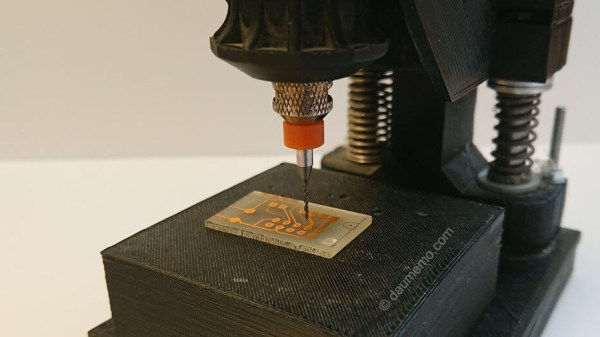
If you make printed circuit boards the old fashioned way by etching them yourself, you may need to drill a lot of holes; even surface-mount converts still need header pins on occasion. But, drilling these holes by hand often leads to broken drill bits, which always seems to happen with one un-drilled hole and no spare bits left. [Daumemo] came up with a solution: a 3D printed drill press for a Dremel or similar rotary tool.

While you can buy commercial presses designed to fit these tools, there’s a certain satisfaction to building your own, and if you have a well-stocked parts bin you might even finish it before a mail-ordered version could arrive. Certainly you could do it at lower cost. The design is straightforward, and uses printed parts augmented with “reprap vitamins” (i.e. the non-printable, typically metal, components). If you’ve ever built — or repaired — a 3D printer, you may have these pieces already: a couple of LM8UU bearings, some 8 mm steel rod, and a pair of springs seem like the most esoteric parts required, although even these could probably be substituted without much trouble.

Only a few pieces need to be printed: a base is outfitted with a removable table for holding the workpiece, while a lever actuates the frame holding the tool. [Daumemo] chose to print the design in ABS, but found that it flexes a little too much, occasionally requiring some care during use — a stiffer filament such as PLA might yield better results. Overall, though, this seems like a great project for that 3D printer you haven’t used in a while.

Be sure to check out the video of the press in action, after the break.

Continue reading “Print A Drill Press For Your Printed Circuit Boards”

diy foot switch

Foot Pedal Switch Specifically Made For PCB Drilling

Using the Toner-Transfer and Etch method for making prototype circuit boards is fairly common. One downside to this process is that any holes still need to be drilled. [Giorgos] hand drills boards all the time. He has a Dremel with a drill press attachment but he still prefers using a small pen-style mini drill to make the holes. There is one problem with this tool though, the on/off switch is in an non-ergonomic location. After flipping the switch tens of times during a drill job, [Giorgos] has felt some digit discomfort. He knew there had to be a better way.

His solution: a foot pedal on/off switch. This isn’t some off-the-shelf foot switch, [Giorgos] made it from parts and pieces kicking around in one of his junk drawers. The foot pedal frame is made from acrylic sheet. A couple of hinges allow the pedal to press down on an old switch, very similar to the ones found in guitar effect pedals. This switch was heavy-duty and had a strong spring that easily pops the switch and pedal back up after being pressed.

Wiring was easy, the positive lead of the DC wall wart was split and attached to the pedal’s switch. Pressing the switch makes or breaks the power connection, turning the hand-held drill on and off. [Griorgos] solve his ergonomic problem and cleaned out his junk drawer without spending a dime. We’d say that’s a triple win!

PCB Drill Microscope

PCB Drill Press Gets A Microscopic Upgrade

If you get into more complicated PCB design, you’ll find the need to drill tiny and accurate holes much more often. Wouldn’t it be nice to have a precise way of doing that? Maybe even something as simple as strapping a $10 USB digital microscope to it?

That was [mlerman’s] thought anyway, and from the looks of it, it seems to work quite well! If you already have a PCB drill press then it’s just a matter of installing the microscope opposite the drill — align it to the center point with some cross hairs and boom you’re in business.

But if you don’t yet have a PCB drill, [mlerman’s] got you covered there too, as he explains in great detail how to modify a cheap drill press into an inverted PCB drill press.

Inverted PCB Drill Press

Wait, why is it inverted? Besides making more room for the USB microscope to sit, it also ensures the microscope lens doesn’t get covered in the PCB fairy dust that would fall on it if it were in a normal orientation.

[via Embedded-Lab]