Should Have Used A Vacuum Tube 555

“You should have used a 555” has become a bit of a meme around these parts lately, and for good reason. There seems to be little that these ubiquitous chips can’t be used for, and in a world where code often substitutes for hardware, it’s easy to point to instances where one could have just used a simple timer chip instead.

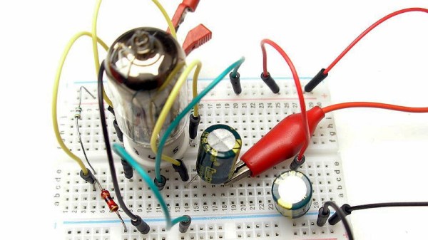
Definitely not in the meme category, though, is this overkill vacuum tube 555 timer. It comes to us via [David Lovett], aka [Usagi Electric], who has lately caught the “hollow state” electronics bug and has been experimenting with all sorts of vacuum tube recreations of circuits we’re far more used to seeing rendered in silicon than glass. The urge to replicate the venerable 555 in nothing but vacuum tubes is understandable, as it uses little more than a pair of comparators and a flip-flop, circuits [David] has already built vacuum tube versions of. The only part left was the discharge transistor; a pentode was enlisted to stand in for that vital function, making the circuit complete.

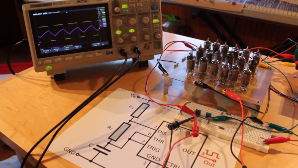
To physically implement the design, [David] built a large PCB to hold the 18 vacuum tubes and the handful of resistors and capacitors needed. Mounted on eight outsized leads made from sheet steel, the circuit pays homage to the original 8-pin DIP form of the 555. The video below shows the design and build process as well as testing of all the common modes of operation for the timer chip.

You can check out more of our coverage of [David]’s vacuum tube adventures, which started with his reverse-engineering of an old IBM logic module. And while he did a great job explaining the inner workings of the 555, you might want to take a deeper dive into how the venerable chip came to be.

Continue reading “Should Have Used A Vacuum Tube 555”

Chasing A Long-Obsolete Tube

Regular readers will know that here at Hackaday we have a penchant for poking fun at the more silly end of the audiophile world, with its dubious accessories and purple prose. It’s worth remembering though that this is not representative of the whole discipline of audio design, indeed the quest for perfect audio reproduction contains plenty of complex engineering problems.

We’re indebted to [macsimski] then for sending us a link to a page from Phaedrus Audio from a year or two ago, in which they discuss the history of an unusual pentode tube used as an impedance converter in a series of legendary post-war microphones. It’s unlikely that you’ll have a Neumann U47 or U48 broadcast microphone on your bench, but even so the story behind their design is one that should fascinate anyone.

It takes us back to the period immediately following the Second World War, when German electricity supplies were varied and unreliable, and radio receivers designed for them required new tubes from the manufacturers. Among these was the VF14, with an unusual high-voltage heater designed such that two of them could be connected in series across the supply. This and its compact shape prompted its selection for the professional microphones, even though its performance was so poor that only  a third of the production passed the performance test.

Since it passed out of production in the early 1950s the remaining components are extremely rare, and the majority of those surviving do not meet the performance characteristics of the microphone. The Phaedrus write-up goes into significant technical detail which should be of note to anyone with an interest in tubes, and ends up with their reason for it all, a plug-in hardware simulation of the original tube’s properties. Vintage capacitor microphones may be out of the ordinary for Hackaday, but it’s still a good read.

For a bit more on capacitor microphones it’s worth a look at our dive into electrets.

Header image: JacoTen / CC BY-SA 3.0

A 3.3 V Tube Preamp Without An Inverter

If you’ve ever worked with vacuum tubes, you’ll probably have a healthy appreciation for high voltage power supplies. These components require higher potentials to get those electrons moving, or so we’re told. It’s not the whole truth though, as [Albert van Dalen] demonstrates with his tube preamplifier running from only 3.3 V. If your first thought is that he must have made a flyback converter to step that voltage up to something more useful then you’re in for a surprise, because the single 6J6 pentode really does run from just 3.3 volts. Even its heater, normally supplied with 6.3 V, takes the lower voltage.

The circuit appears at first sight to be a conventional single-ended design, but closer examination reveals a grid bias circuit more reminiscent of a bipolar transistor. This results in a positive grid voltage rather than the more usual negative, and an unusually high 0.3 mA grid current. The cathode current is only  0.15 mA, but the preamplifier delivers a 3.5x gain. There is more detail on his website.

It would be interesting to subject this circuit to a full audio analysis and comparison with a more conventional design. As with so much in the world of audio there’s some smoke and mirrors around what constitutes the so-called “valve sound”, and it’s a question whether the satisfaction comes through the sound itself or the bragging rights of having a unit with a vacuum tube on show.  Still, this is a simple enough design which takes few resources to build, so we look forward to seeing further experimentation. Careful though – down the vacuum audio route can lie folly.

A Cake Tin Makes A Great Tube Amp Chassis

If you have ever had a go at building a tube-based project you will probably be familiar with the amount of metalwork required to provide support structures for the tubes themselves and the various heavy transformers and large electrolytic capacitors. Electronic construction sixty years ago was as much about building the chassis of a project as it was about building the project itself, and it was thus not uncommon to see creative re-use of a chassis salvaged from another piece of equipment.

This morning we stumbled upon a rather nice solution to some of the metalwork woes facing the tube constructor courtesy of [Bruce], who built his tube audio amplifier on a chassis made from a cake tin and with its transformers housed in decorative display tins.

The circuit itself is a straightforward single-ended design using an ECL82 triode-pentode on each stereo channel, and comes courtesy of [Nitin William]. The power supply is on-board, and uses a pair of silicon diodes rather than another tube as the rectifier.

It’s true that [Bruce] has not entirely escaped metalwork, he’s still had to create the holes for his tubes and various mountings for other components. But a lot of the hard work in making a tube chassis is taken care of with the cake tin design, and the result looks rather professional.

We have something of a personal interest in single-ended tube amplifiers here at Hackaday, as more than one of us have one in our constructional past, present, or immediate futures. They are a great way to dip your toe in the water of tube amplifier design, being fairly simple and easy to make without breaking the bank. We’ve certainly featured our share of tube projects here over the years, for example our “Groove tube” round-up, or our look at some alternative audio amplifiers.

Retrotechtacular: We Heard You Like Tubes, So Here’s A Film About Tube Tubes From The Webtubes

EF80

This lovely little number is the EF80 pentode thermionic valve, or vacuum tube, made by Mullard beginning in 1950. They were used in radio and radar applications, but most of them wound up in VHF television sets. This week’s Retrotechtacular takes a close look at the assembly of and on-site materials production for the EF80 in particular.

The film begins with slow and careful hand assembly of an EF80. The cathode is inserted into a mica disc, and a series of three grids are placed over the cathode. The semicircular anode sits around the outermost grid. Another mica disc is placed on top which does triple duty as a spacer, a base for the getter/plate assembly, and a firewall against the getter flash.The dark lining of the upper part of the tube is the residue of the vaporized getter, which is heated after the first stage of air removal.

Before the vacuuming begins, the inner assembly is mounted on a glass base with nine pins that have been pre-bent to meet the inner assembly wires. The heater, dissipating shield, and a meshy cylinder are added, and then the getter on its plate. A tube is slipped over the assembly and fused to the base in a jig, forming an airtight seal. Continue reading “Retrotechtacular: We Heard You Like Tubes, So Here’s A Film About Tube Tubes From The Webtubes”