ESP8266 Uses LiFi To Get On WiFi

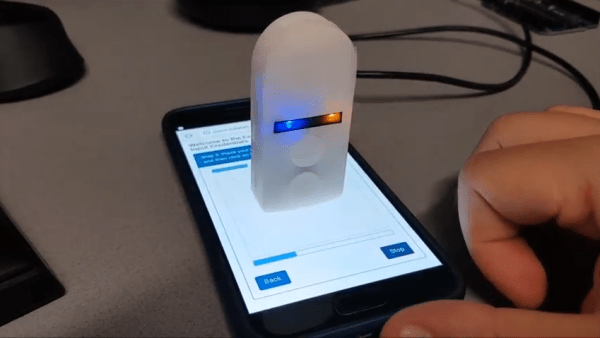
Connecting your shiny new ESP8266 to WiFi can be as simple or as complicated as you please. Most people decide to manually add it. Some people find clever ways to make the bloody thing connect itself. [Eduardo Zola] transfers his WiFi password using the flashing light of a smartphone screen.

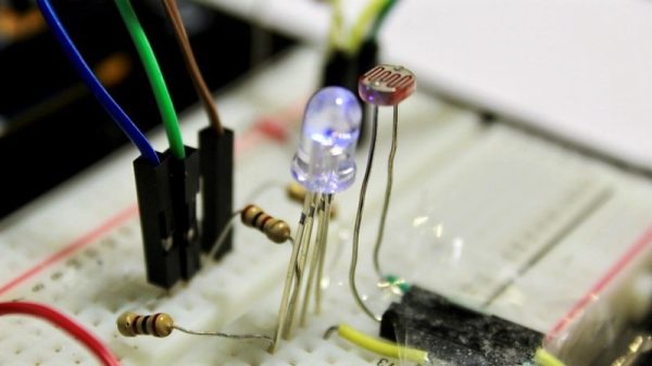
A simple photo-resistor and a bit of tinkering allows him to easily send credentials — or any data really — to his ESP8266, through the power of LiFi. Short for Light Fidelity, LiFi transmits data using light with on and off states representing digital values. It can use visible light, or reach into either the ultraviolet or infra-red radiation if need be. For the nitty-gritty details on the subject, check out our primer on LiFi.

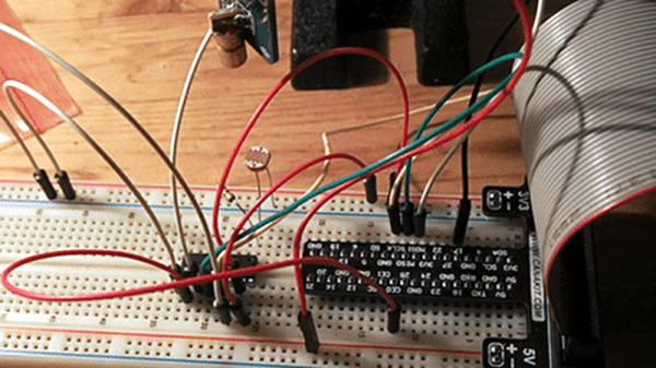
 A flashing LCD screen and a photo-resistor barely make the cut for a one-way LiFi system, but [Eduardo Zola] makes it work. The approach is to build a resitor divider and watch an input pin on the ESP for changes.

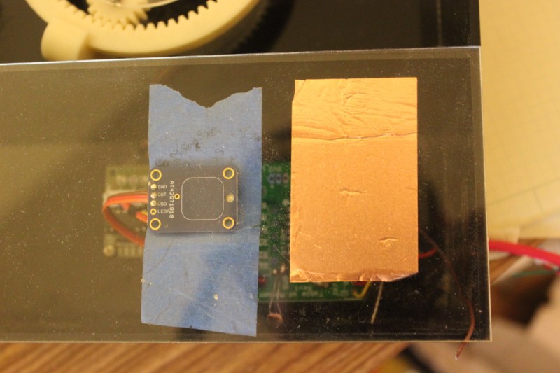
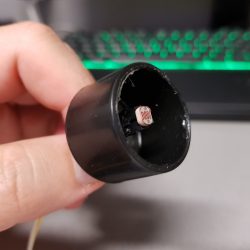
The trick is to keep ambient light out of the mix. The test sensor shown here places the LDR in a black cap, but [Eduardo] 3D-Printed a slick little enclosure for his reverse flashlight so it fits flush with the phone screen. One click and about half a minute of a flashing screen later, and the Wi-Fi credentials are transferred. This circuit could really be added onto any project, for short data transfers. With a bit more work on the sensor circuit, speed could be improved with the limiting factor being the timing on the phone screen itself.

Since the ESP8266 has its own WiFi connection, it’s likely you’ll use that for data transfer once the LiFi gets it onto the network. But any situation where you don’t have a full user input or a network connection could benefit from this. Pull out that old scrolling LED matrix project and add this as a way to push new messages to the device!
Continue reading “ESP8266 Uses LiFi To Get On WiFi”

Color Sensor From An RGB LED And A Photocell

When you need to quantify the color of an object, you’ve got quite a few options. You can throw a Raspberry Pi camera and OpenCV at the problem and approach it through software, or you can buy an off-the-shelf RGB sensor and wire it up to an Arduino. Or you can go back to basics and build this reflective RGB sensor from an LED and a photocell.

The principle behind [TechMartian]’s approach is simplicity itself: shine different colored lights on an object and measure how much light it reflects. If you know the red, green, and blue components of the light that correspond to maximum reflectance, then you know the color of the object. Their sensor uses a four-lead RGB LED, but we suppose a Neopixel could be used as well. The photosensor is a simple cadmium sulfide cell, which measures the intensity of light bouncing back from an object as an Arduino drives the LED through all possible colors with PWM signals. The sensor needs to be white balanced before use but seems to give sensible results in the video below. One imagines that a microcontroller-free design would be possible too, with 555s sweeping the PWN signals and op-amps taking care of detection.

And what’s the natural endpoint for a good RGB sensor? A candy sorter, or course, of which we have many examples, from the sleek and polished to the slightly more hackish.

Continue reading “Color Sensor From An RGB LED And A Photocell”

Fail Of The Week: Museum Buttons

Museum exhibits are difficult to make, and they’re always breaking down; especially the interactive ones. This is a combination of budget, building a one-off, and the incredibly harsh abuse they take from children.

My first exhibit is an interactive laser show that turns waveforms from music into laser patterns, and different types of music have very different patterns. I knew from talking to the museum staff that industrial buttons were a necessity, but it turns out that industrial buttons are made under the assumption that tiny creatures won’t be constantly mashing, twisting, and (ew ew ew) licking the buttons. After a while, the buttons (and poor knob) were trashed.

The second exhibit is also interactive, but in this case it’s just a simple button that turns on a thing for a while, then shuts it off. You can read more about the Periodic Table of Motion on the project page. Here I thought; let’s use capacitive touch, put the sensor behind two layers of acrylic for protection, and then there won’t be any moving parts to break. I built a bunch of units, tested it for weeks, then installed it. Instant failure despite my diligence.

Something is different about the installation from my test environment. It might be the second layer of acrylic contributing. Maybe it’s the power supply and a strange ground issue. Maybe the room’s fluorescent lights are creating an electromagnetic field that is interrupting the sensor, or the carpet is causing static buildup that is somehow causing the midichlorians to reverse polarity and discharge through the base plate of prefabulated aluminite. In some of the cells, the button doesn’t work. In other cells it is extremely sensitive. In one column of the table (columns share a common piece of acrylic among 5 cells), a single touch will trigger all 5.

The circuit is an ATtiny with a 2.2M resistor between two pins, one of which connects via a short wire to a soldered connection to a piece of copper tape on the underside of an acrylic piece. The ATtiny is using the capsense library, which has features for automatic recalibration. Because of the way it is installed, I can’t reprogram them to adjust their sensitivity while inside the enclosure, so tweaking them post-install is not an option. I thought I could isolate the problem and use an existing capacitive touch sensor breakout of the AT42QT1010 hooked up to just power, but it had the exact same issue, meaning it’s either the power supply, the enclosure, or the room.

Side-by-side tests of copper tape+Arduino and AT42QT1010 had similar problems.

There are three paths I can go down now:

  1. Find the problem and solve it
  2. Switch to a photoresistor
  3. Petition Hackaday for a better solution

Finding the problem and solving it will be a long and difficult path, especially since the museum environment is somehow and inexplicably different from the test environment. The photoresistor option has promise; when the user puts their hand over the paper button the light level changes. Some early testing indicates that it is easy to detect instantaneous change, and a trailing average and adjusting threshold make it robust enough for changing lighting conditions throughout the day. Further, it’s a simple change to the code, and the existing circuit board will accommodate the adjustment.

As for the third option…

What have you done for child-compatible touch interfaces that are robust enough to handle uncertain environments and harsh abuse? What buttons, knobs, and other interactive elements have you used?

Automatic Resistance: Resistors Controlled By The Environment

Resistors are one of the fundamental components used in electronic circuits. They do one thing: resist the flow of electrical current. There is more than one way to skin a cat, and there is more than one way for a resistor to work. In previous articles I talked about fixed value resistors as well as variable resistors.

There is one other major group of variable resistors which I didn’t get into: resistors which change value without human intervention. These change by environmental means: temperature, voltage, light, magnetic fields and physical strain. They’re commonly used for automation and without them our lives would be very different.

Continue reading “Automatic Resistance: Resistors Controlled By The Environment”

Raspberry Pi Communication Via LASER

[Nick Touran] wanted to make two Raspberry Pi’s communicate wirelessly. There are lots of options, but [Nick] used a LASER and a photoresistor, along with Morse code. If you don’t find Morse code fancy enough, you could always refer to it as OOK (on/off keying). The circuit uses a common LASER module and an ordinary photoresistor that varies in resistance based on light. A resistor forms a voltage divider with the photoresistor and an external A/D reads the resulting voltage.

The circuit works, but we couldn’t help but notice a few items. Not all photoresistors are as sensitive to the same light wavelengths, so for the maximum range you’d want to pick a particular photoresistor.  While the analog to digital converter is certainly workable, we couldn’t help but wonder if you couldn’t set up the divider to use the inherent threshold of the Raspberry Pi’s input pins for a simpler circuit. Of course, if you used the same technique with an Arduino, you could use the built-in A/D converter, and the A/D converter is probably easier to get working.

Continue reading “Raspberry Pi Communication Via LASER”

Power Meter

Solar Panel System Monitoring Device Using Arduino

[Carl] recently upgraded his home with a solar panel system. This system compliments the electricity he gets from the grid by filling up a battery bank using free (as in beer) energy from the sun. The system came with a basic meter which really only shows the total amount of electricity the panels produce. [Carl] wanted to get more data out of his system. He managed to build his own monitor using an Arduino.

The trick of this build has to do with how the system works. The panel includes an LED light that blinks 1000 times for each kWh of electricity. [Carl] realized that if he could monitor the rate at which the LED is flashing, he could determine approximately how much energy is being generated at any given moment. We’ve seen similar projects in the past.

Like most people new to a technology, [Carl] built his project up by cobbling together other examples he found online. He started off by using a sketch that was originally designed to calculate the speed of a vehicle by measuring the time it took for the vehicle to pass between two points. [Carl] took this code and modified it to use a single photo resistor to detect the LED. He also built a sort of VU meter using several LEDs. The meter would increase and decrease proportionally to the reading on the electrical meter.

[Carl] continued improving on his system over time. He added an LCD panel so he could not only see the exact current measurement, but also the top measurement from the day. He put all of the electronics in a plastic tub and used a ribbon cable to move the LCD panel to a more convenient location. He also had his friend [Andy] clean up the Arduino code to make it easier for others to use as desired.

Auto-Meter Reader Feeder Keeps Meter-Maids At Bay

Planting your car just about anywhere almost always comes at a price; and, if you’re overdue for your return, odds are good that you’ll end up paying a much steeper price than intended. Parking meters are wonderful devices at telling the authorities just how much time you have left until you’re ticketworthy. [Zack] figured that five–even ten minutes late—is an absurd reason to pay a fine, so he’s developed a tool that will preload a meter with a few extra coins when the authorities get too close.

The law-enforcement detection system puts together of number of tools and techniques that we’re intimately familiar with: 3D printing, Arduino, a photoresistor, and a proximity (PIR) sensor. At the code level, [Zack] filters his analog photo resistor with a rolling average to get a clean signal that triggers both by day and by night. The trigger? Two possibilities. The PIR sensor detects curious law enforcement officers while the filtered photoresistor detects the periodic twirling siren lights. Both events will energize a solenoid to drop a few extra coins through a slide and into the meter slot.

For a collection of well-known components, [Zack] could’ve packed his contraption into a Altoids Tin and called it a day. Not so. As an interaction designer, looks could make or break the experience. For this reason, he opts for a face-hugging design with a steampunk twist. Furthermore, to achieve compatibility across a range of devices, [Zack’s] CAD model is the result of adjusting for various meter profiles from images he snapped in the urban wilderness. The result? A clean, authentic piece of equipment compatible with a family of meters.

For the shrewd-eyed observers, [Zack’s] first video post arrived online in 2011, but his work later resurfaced at a presentation in the 2015 Tangible, Embedded, and Embodied Conference by his former design instructor [Eric Paulos], who was eager to show off [Zack’s] work. For a deeper dive into the upcoming second edition, head on over to [Zack’s] image feed.

Continue reading “Auto-Meter Reader Feeder Keeps Meter-Maids At Bay”