RC Drag Racing Christmas Tree And Speed Trap

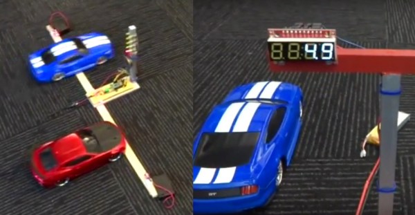
In the drag racing world, a Christmas tree is the post at the start line that sequentially lights up a set of yellow lights followed shortly after by a green light to tell the drivers to go, the lights obviously giving it its seasonal name. Included at the base of the tree are lasers to detect the presence of the cars.

[Mike] not only made his own Christmas tree for his RC cars, but he even made an end-of-track circuit with LED displays telling the cars how long they took. Both start and finish hardware are controlled by Pololu Wixel boards which has TI CC2511F32 microcontrollers with built-in 2.4 GHz radios for wireless communications.

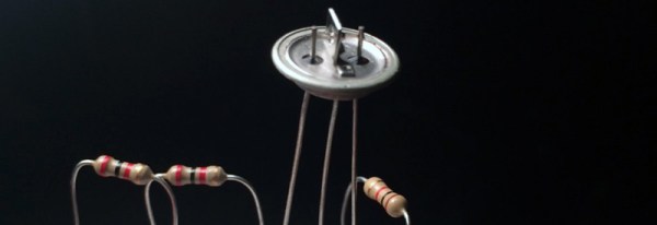
In addition to the LEDs, the Christmas tree has a laser beam using a 650nm red laser diode for each car at the start line that’s aimed at a TEPT5600 phototransistor. If a car crosses its beam before the green light then a red light signals the car’s disqualification.

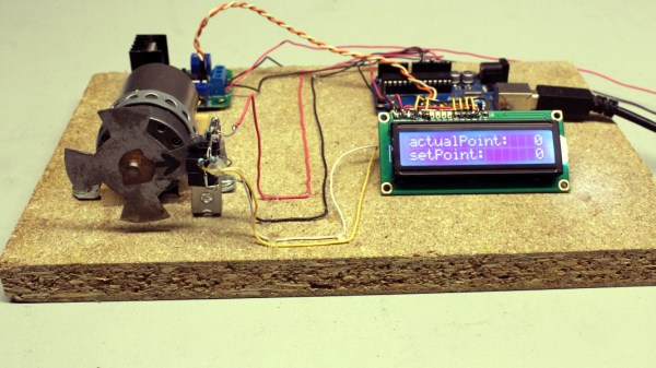
The end-of-track circuit has 7-segment displays for each car’s time. [Mike] designed the system so that the Christmas tree’s microcontroller tells the end-of-track circuit’s microcontroller when to reset the times, start the times, and clear the times should there be a disqualification. The finish line controller has lasers and phototransistors just like the starting line to stop the timers.

Oh, and did we mention that he also included 1980’s car racing game sounds? To see and hear it all in action check out the video after the break. If the cars seem a little drunk it’s because pushing left or right on the controller turns the wheel’s fully left or right.

Continue reading “RC Drag Racing Christmas Tree And Speed Trap”

Hackaday Prize Entry: Germanium Vision

The first digital cameras didn’t come out of a Kodak laboratory or from deep inside the R&D department of the CIA or National Reconnaissance Office. The digital camera first appeared in the pages of Popular Electronics in 1975, using a decapsulated DRAM module to create fuzzy grayscale images on an oscilloscope. For his Hackaday Prize project, [Alexander] is recreating this digital camera not with an easy to use decapsulated DRAM, but with individual germanium transistors.

Phototransistors are only normal transistors with a window to the semiconductor, and after finding an obscene number of old, Soviet metal can transistors, [Alex] had either a phototransistor or a terrible solar cell in a miniaturized package.

The ultimate goal of this project is to create a low resolution camera out of a matrix of these germanium transistors. [Alex] can already detect light with these transistors by watching a multimeter, and the final goal – generating an analog NTSC or PAL video signal – will “just” require a single circuit duplicated hundreds of times.

Digital cameras, even the earliest ones built out of DRAM chips, have relatively small sensors. A discrete image sensor, like the one [Alex] is building for his Hackaday Prize entry, demands a few very interesting engineering challenges. Obviously there must be some sort of lens for this image sensor, so if anyone has a large Fresnel sitting around, you might want to drop [Alex] a line.

The HackadayPrize2016 is Sponsored by:

Flexible Phototransistor Will Make Everything Subtly Better In The Future

University of Wisconsin-Madison is doing some really cool stuff with phototransistors. This is one of those developments that will subtly improve all our devices. Phototransistors are ubiquitous in our lives. It’s near impossible to walk anywhere without one collecting some of your photons.

The first obvious advantage of a flexible grid of phototransistors is the ability to fit the sensor array to any desired shape. For example, in a digital camera the optics are designed to focus a “round” picture on a flat sensor. If we had a curved surface, we could capture more light without having to choose between discarding light, compensating with software, or suffering the various optical distortions.

Another advantage of the University’s new manufacturing approach is the “flip-transfer” construction method they came up with. They propound that their method produces a vastly more sensitive device. The sensing silicon sits on the front of the assembly without any obstructing material in front; also the metal substrate it was built on before flipping is reflective; also increasing the sensitivity.

All in all very cool, and we can’t wait for phone cameras, with super flat lenses, infinite focus, have no low light capture issues, and all the other cool stuff coming out of the labs these days.

Video Gives You The Basics Of DIY Rotary Encoders

Is it really possible to build a rotary encoder out of a flattened tin can and a couple of photodetectors? Sure it’s possible, but what kind of resolution are you going to get from such a contraption? Is there any way that you’d be able to put them to work in a DIY project like a CNC router? If you pay attention to the basics then the answer is yes, and [HomoFaciens] wants to prove that to you with this detailed video on homebrew encoder design.

Faithful Hackaday readers will no doubt recognize [HomoFaciens] from a number of prior appearances on these pages, including this recent hardware store CNC router build. When we first ran across his builds, we admit a snicker or two was had at the homemade encoders, but if you watch the results he manages to get out of his builds, you quickly realize how much you can accomplish with very little. The video is a primer on encoder design, walking you through the basics of sensing rotation with phototransistors, and how a pair of detectors is needed to determine the direction of rotation. He also discusses the relative merits of the number of teeth in the chopper; turns out more isn’t necessarily better. And in the end he manages to turn a car wiper motor into a high-torque servo, which could be a handy trick to have filed away.

Continue reading “Video Gives You The Basics Of DIY Rotary Encoders”

Triple Sensor Mailbox Alert Really Delivers

Messing with the U.S. Mail is not something we generally recommend. But if you build your own mailbox like [Bob] did, you stand a much better chance of doing what you want without throwing up any flags.

Speaking of throwing up flags, one of the coolest parts of this project is the toy mailbox inside the house that monitors the activity of the real box. When there is mail waiting, the flag on the toy mailbox goes up. Once [Bob] retrieves the mail, the flag goes back down automatically. A magnet in the real box’s flag prevents false alarms on the toy box provided the Flag Raised On Outgoing protocol is followed. Best of all, he built in some distress handling: If the mailbox door is left hanging open or the battery is low, the toy mailbox waves its flag up and down.

So, where do the three sensors come in? A magnetic reed switch on the wall of the real mailbox pairs with a magnet in the flag. To determine whether the door is open, [Bob] initially used another magnetic reed switch on the underside of the box. This didn’t work well in wet weather, so he switched to a mechanical tilt sensor. An IR LED on the ceiling and a phototransistor on the floor of the box work together to detect the presence of mail.

[Bob]’s homebrew mailbox has a false back that hides a PIC 16F1825. When the door opens, the PIC wakes up, turns on a MOSFET, and checks the battery level. It waits two minutes for the mailman to do his job and then reads the flag state. After comparing the IR LED and phototransistor’s states, it sends a message to the toy mailbox indicating the presence or absence of mail.

The toy mailbox holds a modified receiver board and a servo to control its flag. [Bob] has made the code and schematics available on his site. Walk-through video is after the jump.

Continue reading “Triple Sensor Mailbox Alert Really Delivers”

Light Pen Draws On LED Matrix

dot-matrix01

Who needs a 1920×1080 OLED display when you can have an 8×8 matrix of LED goodness? That’s the question [Kathy] asked when she built this LED matrix light pen project. It looks simple enough – a 64-LED matrix illuminates as the pen draws shapes. But how does the circuit know which LED is under the pen? Good old fashioned matrix scanning is the answer. Only one LED is lit up at any time.

[Kathy] used a pair of 74LS138 3-to-8 line decoders to scan the matrix. The active low outputs on the ‘138 would be perfect for a common cathode matrix. Of course [Kathy] only had a common anode matrix, so 8 PNP transistors were pressed into service as inverters.

The pen itself is a phototransistor. [Kathy] originally tried a CdS photoresistor, but found it was a bit too slow for matrix scanning. An LM358 op-amp is used to get the signal up to a reasonable level for an Arduino Uno to detect.

The result is impressive for such a simple design. We’d love to see someone use this platform as the start of an epic snake game.

A Mini Op-Amp Based Line Following Robot

LineRobot

There’s no denying it. Super small robots are just cool. [Pinomelean] has posted an Instructable on how to create a mini line following robot using only analog circuitry. This would make a great demo project to show your friends and family what you’ve been up to.

Analog circuitry can be used instead of a microcontroller for many different applications, and this is one of them. The circuit consists of two op-amps that amplify the output of two phototransistors, which control each motor. This circuit is super simple yet very effective. The mechanical system is also quite cool and well thought out. To keep things simple, the motors drive the wheel treads, rather than directly through an axle. After the build was completed, the device needed to be calibrated by turning potentiometers that control the gain of each op-amp. Once everything is balanced, the robot runs great! See it in action after the break.

While not the smallest line follower we have seen, this robot is quite easy to reproduce. What little robots have you build lately? Send us a tip and let us know!

[via Embedded Lab]

Continue reading “A Mini Op-Amp Based Line Following Robot”