Fail Of The Week: This Flash Drive Will NOT Self-Destruct In Five Seconds

How hard can it be to kill a flash drive? Judging by the look of defeat on [Walker]’s face in the video below, pretty darn hard.

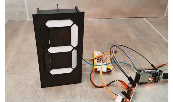
To bring you up to speed, and to give the “Mission: Impossible” reference in the title some context, it might be a good idea to look over our earlier coverage of [Walker]’s Ovrdrive project. It started way back in 2022 with the idea that some people might benefit from a flash drive that could rapidly and covertly render the data stored on it, err, “forensically unavailable.” This would require more than just erasing the data, of course, so [Walker] began looking at ways to physically kill a memory chip. First up was a voltage doubler to apply voltage much greater than the absolute maximum rating of 4.6 V for any pin on the chip. That corrupted some files on the flash chip, enough of a win to proceed to a prototype that actually succeeded in releasing the Magic Smoke.

But sadly, that puff of smoke ended up being a fluke. [Walker] couldn’t repeat the result, at least not with the reliability required by people for whom data privacy is literally a life-or-death matter. To increase the odds of a kill, he came up with an H-bridge circuit to reverse the polarity of the memory chip’s supply. Surely that would kill the chip, and from the thermal camera images, it sure looked promising. But apparently, even 167°C isn’t enough to forensically disable the chip, which kind of makes sense from the point of view of reflow survivability.

What’s next for [Walker]? He says he’s going to team up his overvoltage and reverse-polarity methods for one last shot, but after that, he’s about out of reasonable options. Sure, a thermite charge or a vial of superacid would do the trick, but neither is terribly covert. If you’re going to go that way, you might as well just buy a standard flash drive and throw it in the microwave or a blender. And we need to remember that this may be something the drive’s owner needs to do with jack-booted thugs kicking in the door, or possibly at gunpoint. It wouldn’t do to be too conspicuous under such circumstances. That’s why we like the “rapid power cycling” method of triggering the drive’s self-destruct sequence; it could easily be disguised as shaking hands in a stressful situation.

Who knew that memory chips were this robust? Kudos to [Walker] for getting the project as far as he did, and we’re still rooting for him to make it work somehow.

Continue reading “Fail Of The Week: This Flash Drive Will NOT Self-Destruct In Five Seconds”

One Stepper Plus A Whole Bunch Of Magnets Equals A Unique Seven-Segment Display

Sometimes the cost of simplicity is extra complexity. It seems counterintuitive, but it seems to be true. And this single-motor mechanical seven-segment display seems to be a perfect example of this paradox.

On second thought, [aeropic]’s mechanism isn’t really all that mechanically complicated, but there sure was a lot of planning and ingenuity that went into it. The front has a 3D-printed bezel with the familiar segment cutouts, each of which is fitted with a pivoting segment, black on one side and white on the other.

Behind the bezel is a vertical shaft with three wheels, one behind each horizontal segment, and a pair of horizontal shafts, each with two wheels behind each vertical segment. The three shafts are geared to turn together by a single stepper in the base. Each wheel has ten magnets embedded in the outer circumference, with the polarity oriented to flip the segment in front of it to the right orientation for the current digit. It’s probably something that’s most easily understood by watching the video below.

We’ve seen quite a few of these mechanical seven-segment displays lately — this cam-and-servo mechanism comes to mind. We love them all, of course, but the great thing about [aeropic]’s display is how quiet it is — the stepper is mostly silent, and the segments make only a gentle clunk when they flip. It’s very satisfying.

Continue reading “One Stepper Plus A Whole Bunch Of Magnets Equals A Unique Seven-Segment Display”

Handy Continuity Tester Packs Multiple Modes Into A Tiny Package

From Leatherman multitools to oscilloscopes with built-in signal generators and protocol analyzers, there seems no end to tools with multiple personalities. Everybody loves multitaskers because they make it feel like you’re getting more bang for your buck, and in most cases that’s true. But a jack of all trades is seldom master of any, and there are times when even the humble multimeter isn’t the best tool for the job.

With that in mind, [sidsingh] has developed what we think is a very nice dedicated continuity tester. With a goal of using only parts on hand, he had to think small to fit everything into the case he had. So he started with a PIC10LF322 to support all the flavors of continuity testing he wanted to support. In addition to straight continuity, the tester can handle diode testing, detecting shorted or open diodes and even differentiating between regular and Schottky diodes. It also has an LED test mode and an interesting “discontinuity” testing mode — it only sounds its buzzer when continuity is broken. The video below shows that mode in action for finding intermittent cable faults, along with all the other modes.

For an ostensibly single-purpose tool, this tester still manages to pack a lot of tests into one very compact package. Simpler continuity testers are good, too — check out this cheap dollar store build, or this slightly more complicated unit based on an ATtiny85.

Continue reading “Handy Continuity Tester Packs Multiple Modes Into A Tiny Package”

Adjustable Voltage And Polarity Tester

polarity_tester

Instructables user [Rudolf] wrote in to share a handy little tool he created with ham radio operators in mind. Now and again, he found himself connecting to an unknown power supply, and rather than blow out all his expensive radio gear, he decided to put together a simple polarity and voltage tester that can be easily carried out in the field.

The tester features a pair of powerpole connectors, which are used quite often for connecting HAM gear. A PIC12F675 runs the show, acting as an adjustable comparator for detecting voltage levels. By default, his probe glows amber when the supply voltage is below 11.5V, turning green when the supply is between 11.5V and 15V. When the detected voltage is too high, the built-in LED glows a bright red. When the polarity is reversed, the LED flashes red regardless of the supply voltage.

All of these trigger levels can be set in the PIC’s code, which [Rudolf] is kind enough to include on his page, along with schematics for making your own.