When you leaf through a basic electronics textbook, you’ll find chapters describing in detail the operation of the various components. Resistors, capacitors, inductors, and semiconductors. The latter chapter will talk about P and N type regions, introduce us to the diode, and then deal with the transistor: its basic operation, how to bias it, and the like.
We’re all used to conventional resistors, devices that follow Ohm’s Law. When you apply a voltage to a resistor, a current flows through it, and when the voltage is increased, so does the current. Thus if you use a positive resistance device, say a normal resistor, in both the top and the bottom halves of a potential divider, varying the voltage fed into the top of the divider results in the resistor behaving as you’d expect, and the voltage across it increases.
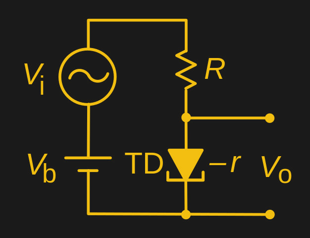
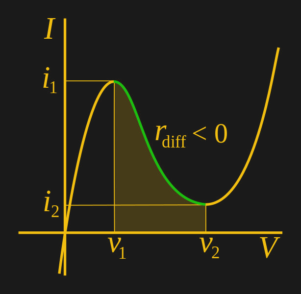
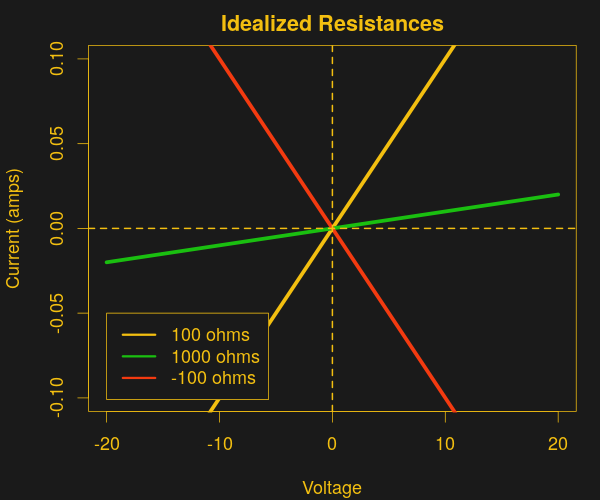 In a negative resistance device the opposite is the case: increasing the voltage across it results in decreasing current flowing through it. When a large enough negative resistance device is used in the lower half of a resistive divider, it reduces the overall current flowing through the divider when the input voltage increases. With less current flowing across the top resistor, more voltage is present at the output. This makes the negative resistor divider into an amplifier.
The tunnel diodes we mentioned above are probably the best known devices that exhibit negative resistance, and there was a time in the early 1960s before transistors gained extra performance that they seemed to represent the future in electronics. But they aren’t the only devices with a negative resistance curve, indeed aside from other semiconductors such as Gunn diodes you can find negative resistance in some surprising places. Electrical arcs, for example, or fluorescent lighting tubes.
It’s unlikely that you will encounter a tunnel diode or other similar electronic component outside the realm of very specialist surplus parts suppliers. We’ve featured them only rarely, and then they are usually surplus devices from the 1960s. But understanding something of how they operate in a circuit should be part of the general knowledge of anyone with an interest in electronics, and is thus worth taking a moment to look at.
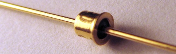
1N3716 tunnel diode header image: Caliston [Public domain].


