CitizenWatt And The Power Of Community

Depending upon where you live in the world, the chances are that your national or local government, or your utility company, has smart meters on their agenda. The idea is that these network-connected energy meters for your gas and electricity supply will allow greater control of energy usage and lead to lower costs through more efficient use of that energy. Bold plans have been advanced for meters that exert control over your higher-power appliances such as water heaters, washing machines, or home heating systems, able to turn them off or on depending on the time of day, spot price of energy, or load on the grid as a whole.

These devices are not without controversy though. Privacy concerns for example, centred on the amount of information about individuals that could be gleaned from the data they collect. Or security, that a vulnerability in an internet-connected electronic device fitted to millions of homes and with control over high-power appliances could be catastrophic if successfully exploited.

In a small area of Paris, they are trying to reap some of the benefits of smart meters for a community without some of those risks. CitizenWatt (French language, Google Translate link) is an open-source smart energy monitor that provides some of the benefits of a smart meter while allowing its owner to retain control of the data it generates by sharing data only with their consent. The entire project was born of an association between Citoyens Capteurs (Citizen Sensors, French language, Google Translate link), the hackEns (French language, Google Translate link) hackspace, the Fabelier FabLab, and the City of Paris.

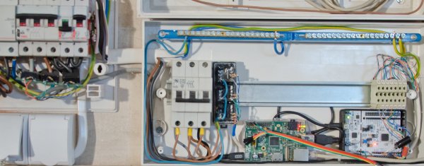
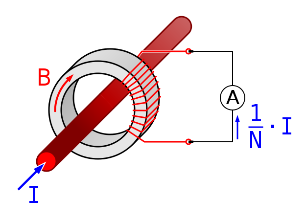
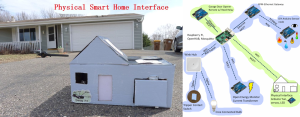
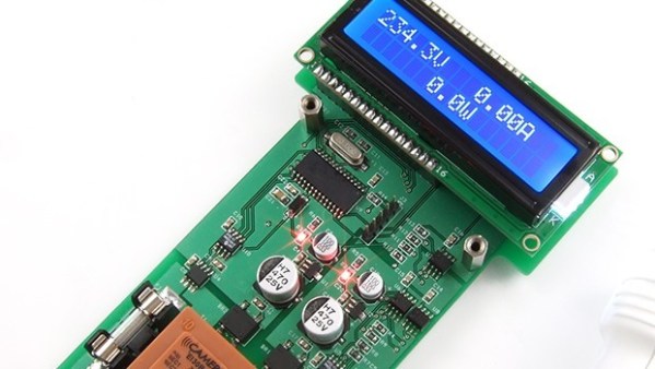
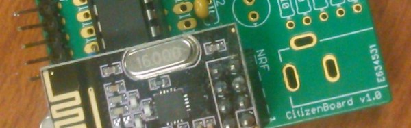
The CitizenWatt system comprises an electricity sensor and a base station. The sensor is a simple battery-powered device that takes the output from a current transformer clamped onto the electricity supply cable and feeds it via an ATMEGA8 microcontroller to a 2.4GHz RF link. The base station is a Raspberry Pi which retrieves the data from the RF, stores it, and allows the user to view it through a web interface. Both the sensor code and hardware files, and the files for the Raspberry Pi base station are freely available on GitHub.

In keeping with the open nature on their project, the CitizenWatt team organised a series of events at which the families who were part of their trial in a Paris suburb were given the chance to build their own sensor boards, for many of them the first time they had handled a soldering iron.

We have seen quite a few smart meters on these pages over the years. There is this one based on a Spark Core, this one based on an ESP8266, and this one provided by a utility company, the data of which can be accessed. CitizenWatt is a worthy project to join them in its own right, but its involvement of a local community of non-makers is what sets it apart. We applad this aspect of the project, and we wish we saw more like it.

Finally, A Power Meter Without Nixies

We’ve had quite a spate of home-brew energy meters on the tip line these days, and that probably reflects a deep inner desire that hackers seem to have to quantify their worlds. Functionally, these meters have all differed, but we’ve noticed a distinct stylistic trend toward the “Nixies and wood” look. Ironically, it is refreshing to see an energy meter with nothing but a spartan web interface for a change.

Clearly, [Tomasz Salwach] had raw data in mind as a design goal, and his Raspberry Pi-based meter delivers. After harvesting current sensing transformers from a bucket of defunct power meter PC boards, [Tomasz] calibrated them with a DIY oscilloscope and wired them and the voltage sensors up to an STM32 Nucleo development board. Data from the MCU goes to the Pi for processing and display as snazzy charts and GUI elements served internally. [Tomasz] was kind enough to include a link to his meter in his tip line post, but asked that we not share it publicly lest HaD readers love the Pi to death. But we can assure you that it works, and it’s kind of fun to peek in on the power usage of a house in Poland in real time.

It’s a nice project that does exactly what it set out to do. But if you missed the recent spate of Nixie-based displays, check out this front hallway meter or this one for a solar-power company CEO’s desk.

Nixie Tubes Adorn Steampunk Solar Power Meter

The appeal of adding Nixie tube displays to a project seems to know no end. First it was Nixie clocks, now it’s Nixie power meters, with the latest addition being this Nixie-Steampunk hybrid solar power monitor.

We’re suckers for a project with a vintage look, and this one pushes all the buttons. Built on commission for a solar power company CEO’s office, [Paul Parry]’s build is based on a Depression-era Metropolitan-Vickers combined voltmeter and ammeter. The huge meters with mirrored scales and the rich wood of the case – our guess is that it’s mahogany – made a great starting point, and after some careful hole drilling, nine IN-18 Nixies were sprouting from the case. A strip of RGB LEDs below decks added the requisite backlighting of the envelopes, and a Raspberry Pi was enlisted to interpret data from the company’s solar farm and drive the tubes and the meters. The project was capped off with a new finish on the case and a couple of fancy brass plaques.

[Paul] sent us the tip for his build after seeing the last power meter we covered, and we have to say they’re both great looking and functional projects. Keep the Nixie projects coming!

Simple USB Power Meter

The USB interface is being increasingly used as a power supply and charging port for all kinds of devices, besides data transfer. A meter to measure the electrical parameters of devices connected to a USB socket or charger would be handy on any hacker workbench. The folks at [electro-labs] designed this simple USB power meter which does just that.

The device measures voltage and current and displays them, along with the calculated power, on the small 0.5″ OLED display. The circuit is built around an ATmega328. To keep the board size small, and reduce component count, the microcontroller is run off its internal 8MHz clock. A low-resistance shunt provides current sensing which is amplified by the LT6106 a high side current sense amplifier before being fed to the 10 bit analog port of the ATmega. A MCP1525 precision voltage reference provides 2.5V to the Analog reference pin of the microcontroller, resulting in a 2.44mV resolution. Voltage measurement is via a resistive divider that has a range of up to 6V. An Arduino sketch reads voltage and current data on the analog ports and displays measurements on the display. The measured data is averaged to filter out noise.

The OLED display has a SPI interface and requires the u8glib library. The project uses all SMD parts, but is fairly easy to assemble by hand and could be a nice starter project if you want to wet your feet on surface mount assembly techniques. It’s designed using SolaPCB EDA software, and the source files for schematic and board layout are available as a ZIP archive. Download the BoM and Arduino code and you have everything needed to build this nifty device.

Thanks to [Abdulgafur] for sending in this tip. And if you are looking for a more comprehensive solution, check the awesome Friedcircuits USB Tester which we reviewed earlier and is available in the Hackaday Store.

Self Built Power Meter Uses Dual Sense Transformers

[Renaud] built a AC power meter from scratch. While commercial power meters like the Kill A Watt are available [Renaud’s] build gives an interesting insight into the methods used.

currentAt the heart of [Renaud’s] design lie two sense transformers. The first is a typical voltage stepdown transformer. This brings the AC line voltage down to +/- 10V, which is more amenable to digital sampling. The second is a current sense transformer. In current transformers the primary is typically a single wire (the AC line in this case) passing through the middle of a ring (see the picture to the right from wikipedia). The secondary is wrapped round the ring. When the secondary coil is shorted a current in the primary wire/coil induces a current in the secondary coil.

In practice, the voltage drop across a low value resistor is used to detect the current in the secondary. Clamp meters use this principle to make non-contact current measurements. Other power meters often use hall effect sensors for current measurements. It will be interesting to see how these methods compare when [Renaud] benchmarks this build.

[Renaud] takes the voltage and current readings from these transformers and samples them with a PIC in order to calculate power. As the AC voltage is periodic [Renaud] uses a method similar to Equivalent Time Sampling (ETS) to combine waveforms from multiple cycles and increase the effective sample rate.

Great stuff [Renaud]!

Model House Models House, Vice-Versa

[Eric Tsai] is on a home-automation rampage. Not content with the usual smartphone-based GUIs, [Eric] built a cardboard model house that models his house. Open the garage door, and the model house’s garage door opens. Open the real front door, and a tiny servo motor opens the cardboard front door.

The model house also comes with a power meter that represents his current power usage, which is certainly useful for figuring out if something electronic has gone grossly wrong. You should watch the video (found after the break) all the way through, here’s the spot where he turns on an electric leaf blower. Despite a little big of lag that’s pretty cool!

But the system doesn’t stop there. Since he can control the garage door and some lights remotely via WiFi, the next logical step is to add a couple of buttons so that the model house can control the real house.

We’ve covered [Eric]’s home before. He set up simple, Arduino-based sensor packages all around his house, connected them together through the pub/sub framework MQTT and added in the open-source OpenHAB software interface. The door sensors connect to a hacked Wink hub. From whether or not his dog is barking to whether his laundry is done, [Eric]’s system knows it all.

Continue reading “Model House Models House, Vice-Versa”

Watt Meter Build Walks You Through Power Measurement Basics

You almost never hear of a DC Watt Meter – one just does some mental math with Volts and Amps at the back of one’s head. An AC Watt Meter, on the other hand, can by pretty useful on any workbench. This handy DIY Digital AC Watt Meter not only has an impressive 30A current range, but is designed in a hand-held form factor, making it easy to carry around.

The design from Electro-Labs provides build instructions for the hardware, as well as the software for the PIC micro-controller at its heart. A detailed description walks you through the schematic’s various blocks, and there’s also some basics of AC power measurement thrown in for good measure. The schematic and board layout are done using SolaPCB – a Windows only free EDA tool which we haven’t heard about until now. A full BoM and the PIC code round off the build. On the hardware side, the unit uses MCP3202 12 bit ADC converters with SPI interface, making it easy to hook them up to the micro-controller. A simple resistive divider for voltage and an ACS-712  Hall Effect-Based Linear Current Sensor IC are the main sense elements. Phase calculations are done by the micro-controller. The importance of isolation is not overlooked, using opto-isolators to keep the digital section away from the analog. The board outline looks like it has been designed to fit some off-the-shelf hand-held plastic enclosure (if you can’t find one, whip one up from a 3D printer).

Although the design is for 230V~250V range, it can easily be modified for 110V use by changing a few parts. Swap the transformer, change the Resistive voltage divider values, maybe some DC level shifting, and you’re good to go. The one feature that would be a nice upgrade to this meter would be Energy measurements, besides just Power. For an inside look at how traditional energy meters work, head over to this video where [Ben Krasnow] explains KiloWatt Hour Meters