Supercon SMD Challenge Gets 3D Printed Probes: Build Your Own

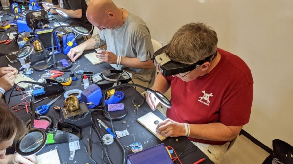
This year was the second SMD challenge at Supercon, so it stands to reason we probably learned a few things from last year. If you aren’t familiar with the challenge, you are served some pretty conventional tools and have to solder a board with LEDs getting progressively smaller until you get to 0201 components. Those are challenging even with proper tools, but a surprising number of people have managed to build them even using the clunky, large irons we provide.

During the first challenge, we did find one problem though. The LEDs are all marked for polarity. However, since we don’t provide super high power magnification, it was often difficult to determine the polarity, especially on the smaller parts. Last year, [xBeau] produced some quick LED testers to help overcome this problem. This year we refined them a bit.

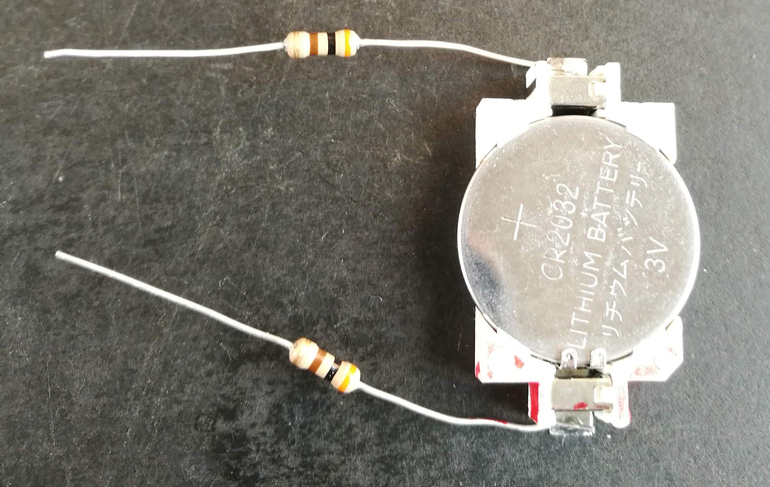
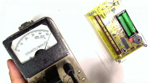
As you can see, the 2018 model was a very clever use of what was on hand. A CR2032 holder powered the probes and the probes themselves were two resistors. If you can get the LED to light with the probes you know which lead is the anode and which is the cathode. A little red ink makes it even more obvious. Continue reading “Supercon SMD Challenge Gets 3D Printed Probes: Build Your Own”

A DIY EMC Probe From Semi-Rigid Coax And An SDR

Do you have an EMC probe in your toolkit? Probably not, unless you’re in the business of electromagnetic compatibility testing or getting a product ready for the regulatory compliance process. Usually such probes are used in anechoic chambers and connected to sophisticated gear like spectrum analyzers – expensive stuff. But there are ways to probe the electromagnetic mysteries of your projects on the cheap, as this DIY EMC testing setup proves.

As with many projects, [dimtass]’ build was inspired by a video over on EEVblog, where [Dave] made a simple EMC probe from a length of semi-rigid coax cable. At $10, it’s a cheap solution, but lacking a spectrum analyzer like the one that [Dave] plugged his cheap probe into, [dimtass] went a different way. With the homemade probe plugged into an RTL-SDR dongle and SDR# running on a PC, [dimtass] was able to get a decent approximation of a spectrum analyzer, at least when tested against a 10-MHz oven-controlled crystal oscillator. It’s not the same thing as a dedicated spectrum analyzer – limited bandwidth, higher noise, and not calibrated – but it works well enough, and as [dimtass] points out, infinitely hackable through the SDR# API. The probe even works decently when plugged right into a DSO with the FFT function running.

Again, neither of these setups is a substitute for proper EMC testing, but it’ll probably do for the home gamer. If you want to check out the lengths the pros go through to make sure their products don’t spew signals, check out [Jenny]’s overview of the EMC testing process.

[via RTL-SDR.com]

Manual 3D Digitizer Works A Bit Like 3-Dimensional Measuring Tape

Digitizing an object usually means firing up a CAD program and keeping the calipers handy, or using a 3D scanner to create a point cloud representing an object’s surfaces. [Dzl] took an entirely different approach with his DIY manual 3D digitizer, a laser-cut and 3D printed assembly that uses rotary encoders to create a turntable with an articulated “probe arm” attached.

Each joint of the arm is also an encoder, and by reading the encoder values and applying a bit of trigonometry, the relative position of the arm’s tip can be known at all times. Manually moving the tip of the arm from point to point on an object therefore creates measurements of that object. [Dzl] successfully created a prototype to test the idea, and the project files are available on GitHub.

We remember the earlier version of this project and it’s great to see how it’s been updated with improvements like the addition of a turntable with an encoder. DIY 3D digitizing takes all kinds of approaches, and one example was this unit that used four Raspberry Pi Zeros and four cameras to generate high quality 3D scans.

The Ins And Outs Of Geiger Counters, For Personal Reasons

There are times in one’s life when circumstances drive an intense interest in one specific topic, and we put our energy into devouring all the information we can on the subject. [The Current Source], aka [Derek], seems to be in such a situation these days, and his area of interest is radioactivity and its measurement. So with time to spare on his hands, he has worked up this video review of radioactivity and how Geiger counters work.

Why the interest in radioactivity? Bluntly put, because he is radioactive, at least for the next week. You see, [Derek] was recently diagnosed with thyroid cancer, and one of the post-thyroidectomy therapeutic options to scavenge up any stray thyroid cells is drinking a cocktail of iodine-131, a radioisotope that accumulates in thyroid cells and kills them. Trouble is, this leaves the patient dangerously radioactive, necessitating isolation for a week or more. To pass the time away from family and friends, [Derek] did a teardown on a commercial Geiger counter, the classic Ludlum Model 2 with a pancake probe. The internals of the meter are surprisingly simple, and each stage of the circuit is easily identified. He follows that up with a DIY Geiger counter kit build, which is also very simple — just a high-voltage section made from a 555 timer along with a microcontroller. He tests both instruments using himself as a source; we have to say it’s pretty alarming to hear how hot he still is. Check it out in the video below.

Given the circumstances, we’re amazed that [Derek] is not only keeping his cool but exhibiting a good sense of humor. We wish him well in his recovery, and if doing teardowns like this or projects like this freezer alarm or a no-IC bipolar power supply helps him cope, then we all win.

Continue reading “The Ins And Outs Of Geiger Counters, For Personal Reasons”

Precision Pantograph Probes PCBs

Electronic components are getting smaller and for most of us, our eyesight is getting worse. When [Kurt] started using a microscope to get a better view of his work, he realized he needed another tool to give his hands the same kind of precision. That tool didn’t exist so he built it.

The PantoProbe is a pantograph mechanism meant to guide a probe for reaching the tiny pads of his SMT components. He reports that he has no longer has any trouble differentiating pins 0.5 mm apart which is the diameter of the graphite sticks in our favorite mechanical pencils.

[Kurt] has already expanded his machine’s capability to include a holder for a high-frequency probe and even pulleys for a pick-and-place variation. There’s no mention of dual-wielding PantoProbes as micro-helping-hands but the versatility we’ve seen suggests that it is only a matter of time.

Four bar linkages are capable of some incredible feats and they’re found all around us. Enjoy one of [Kurt]’s other custom PCBs in his Plexitube Owl Clock, or let him show you to make 3D objects with a laser engraver.

Continue reading “Precision Pantograph Probes PCBs”

Review: The O-scope Mayer D4/WG5 Calibrated Fleshy Test Probe

A selection of probes, from [Jim Williams'] Linear Technology app note 72.
A selection of probes, from [Jim Williams’] Linear Technology app note 72.
It’s not often that we are shown an entirely new class of test equipment here at Hackaday, so it was with some surprise that we recently received the new O-scope Mayer offering. If your most simple piece of test equipment is your own finger, able to measure temperature, detect voltage, and inject a 50 or 60 Hz sine wave, then what they have done is produce a synthetic analogue with a calibrated reading. The idea is that where previously you could only say “Too hot!”, or “High voltage!”, you should now be able to use their calibrated probe to gain an accurate reading.

The O-scope Mayer D4/WG5 Calibrated Fleshy Test Probe is a roughly 4″ (100mm) long cylinder of their InteliMeat™ synthetic finger analogue terminated with a calibrated matching unit and a BNC socket. In the box aside from the instruction leaflet is a BNC lead through which you can connect it to your oscilloscope.

Continue reading “Review: The O-scope Mayer D4/WG5 Calibrated Fleshy Test Probe”

MacGyvering Test Lead Clips

Okay fellow Make-Gyvers, what do you get when you cross a peripheral power cable jumper, a paperclip, springs, and some 3D-printed housings? DIY test lead clips.

Test clips are easily acquired, but where’s the fun in that? [notionSuday] started by removing the lead connectors from the jumper, soldering them to stripped lengths of paperclip, bent tabs off the connectors to act as stoppers, and slid springs over top. Four quick prints for the housings later, the paperclip assembly fit right inside, the tips bent and clipped to work as the makeshift clamp. Once slipped onto the ends of their multimeter probes, they worked like a charm.

Continue reading “MacGyvering Test Lead Clips”