Stuffing A 32-Pin Chip Into A 28-Pin Socket

What’s the difference between a 64k ROM in a 28-pin DIP and a 128k ROM in a 32-pin DIP? Aside from the obvious answers of “64k” and “four pins,” it turns out that these two chips have a lot in common, enough so that it only takes a little bodging to make them interchangeable — more or less.

For a variety of reasons revealed in the video below, [Anders Nielsen] use the SST39SF010, a Flash ROM in a 32-pin DIP, in place of the old standby W27C512, an EEPROM in a 28-pin DIP. To deal with those pesky extra pins on the Flash ROM, [Anders] dug into the data sheets and found that thanks to JEDEC standards, almost everything about the pinouts of the two chips is identical. The only real difference is the location of Vcc, plus the presence of a 16th address bus line on the more capacious Flash ROM.

Willing to sacrifice the upper half of the Flash chip’s capacity, [Anders] set about bodging the 32-pin chip to work in a 28-pin socket. The mods include a jumper from pin 32 to pin 30 on the Flash chip, which puts Vcc in the right place, and adding a couple of pull-up resistors for write-enable and A16. Easy enough changes, but unfortunately, [Anders] chose a Flash ROM with heavily oxidized pins, leading to some cold solder joints and intermittent problems while testing. There’s also the fact that not all boards have room for overhanging pins, a problem solved by adding a socket to create a little vertical clearance.

We found this to be a neat little hack, one that should make it a bit easier to use the wrong chip for the job. If you want to see where [Anders] is using these chips, check out his 6502 in an Arduino footprint or the bring-up of an old XT motherboard.

Continue reading “Stuffing A 32-Pin Chip Into A 28-Pin Socket”

Minimal USB Device Connects With Just A Couple Of Resistors

If you’re like most of us, your basic approach to building something boils down to: “What’s the minimum amount I need to do to get this to work?” It’s not a bad strategy in general, but the minimal build is rarely enough to meet all the requirements, as this extremely minimal but functional USB device illustrates.

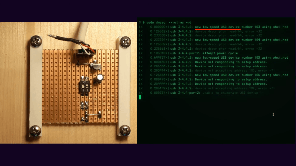
Functional, yes, but as [TM] explains, only if you define functional as being recognized by your operating system. The BOM for that job turns out to be really small — a 3.3-volt regulator, its capacitor, and a pair of resistors connected to a DIP switch. The resistors, 1.5k each, are connected to the D+ and D- lines of the USB connector and pull their respective lines up to 3V3 when their switch is closed. If the D- switch is thrown, it indicates a low-speed connection is requested, while D+ requests a speedier connection. Either way, its enough to get the familiar “USB connect” sound in Windows, and to see it listed in Device Manager or dmesg on Linux.

With no microcontroller to return a device descriptor, not much else happens, of course, but it’s still interesting that so little is needed to at least get the host machine to know that something was plugged in. And that alone has some diagnostic value; as [TM] points out, you could use this circuit to test that the physical port on the host at least minimally works.

He runs through a few other potentially useful scenarios, but really, the best use of something like this is to educate yourself on the lowest levels of USB connection negotiation. If you want to dive deeper into USB-C specifically, we suggest you check out [Arya Voronova]’s “All About USB-C” series.

Continue reading “Minimal USB Device Connects With Just A Couple Of Resistors”

Get Quarantine Fit With This Smart Pull-up Bar

Most gyms are closed right now due to social distancing rules, which is what we’re using as our latest excuse to justify our sloth-like lifestyle. But apparently some people miss working out enough that they’re putting together impromptu home gyms. [Michael Pick] has even outfitted his DIY pull-up station with an Arduino to keep track of his exercise while on lockdown. You may not like it, but this is what peak performance looks like.

Can you beat the HaD high score?

In the video after the break, [Michael] explains the design and construction of the bar itself which technically could be thought of as its own project. Obviously the Arduino counter isn’t strictly necessary, so if you just wanted to know how to put some scraps of wood and suitably beefy rod together in such a way that it won’t rip off the wall when you put your weight on it, this video is for you.

Towards the end of the video, he gets into an explanation of the electronic side of the project. Inside the 3D printed enclosure is an Arduino Pro Mini, a HC-SR04 ultrasonic sensor, and a 1602 serial LCD. Once the gadget has been mounted in the proper position and activated, it will count how many pull-ups [Michael] has done on the screen.

While we historically haven’t seen a whole lot in the way of homebrew exercise equipment, the current COVID-19 situation does seem to be getting the adrenaline flowing for some of you. We recently covered some DIY dumbbells made from hardware store finds that would be an excellent first project for any hackers who’ve recently been ejected from the Matrix and are trying to use their muscles for the first time.

Continue reading “Get Quarantine Fit With This Smart Pull-up Bar”

Two Pins For The Price Of One

One of the most common problems in the world of microcontrollers is running out of resources. Sometimes it’s memory, where the code must be pared down to fit into the flash on the microcontroller. Other times, as [Fabien] found out when he ran out of pins, the limitations are entirely physical. Not one to give up, he managed to solve the problem by using one pin for two tasks. (Google Translate from French)
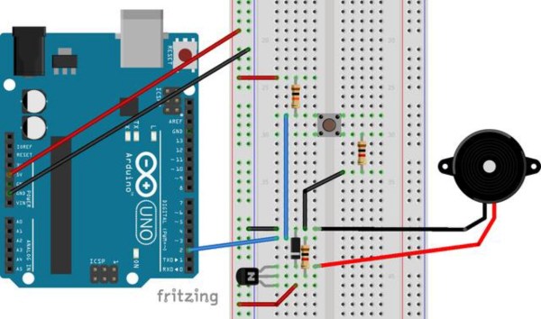
During a recent project, [Fabien] realized he had forgotten to add a piezo buzzer to his project. All of the other pins were in use, though, so his goal was to use one of the input pins to handle button presses but to occasionally switch to output mode when the piezo buzzer was needed. After all, the button is only used at certain times, and the microcontroller pin sits unused otherwise. After a few trials, he has a working solution that manages to neither burn out itself nor the components in the circuit, and none of the components interfere with the other’s normal operation.
While it isn’t the most technically advanced thing we’ve ever seen here, it is a great example of using the tools at your disposal to elegantly solve a problem. More than that, though, it’s a thorough look into the details of pull-up and pull-down resistors, how microcontrollers see voltage as logic levels, and how other pieces of hardware interact with microcontrollers of all different types. This is definitely worth a read, especially if you are a beginner in this world.