Custom Macro Keyboard With Sweet Backlighting

From the smallest 60% keyboards for those with no desk space to keyboards with number pads for those doing data entry all day, there’s a keyboard size and shape for just about everyone. The only problem, even with the largest keyboards, is that they’re still fairly limited in what they can do. If you find yourself wishing for even more functionality, you might want to build something like this custom macro keyboard with built-in LED backlighting.

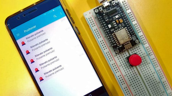
Rather than go with a standard mechanical keyboard switch like a Cherry MX, this build is based around TS26-2 pushbuttons with built-in LED lighting. [atkaper] only really needed one button for managing the mute button on MS Teams, but still built a total of eight switches into this keyboard which can all be individually programmed with different functions. The controller is an Arduino Leonardo and the enclosure was 3D printed.

Paired with the classic IBM Model M keyboard, this new macro keyboard adds plenty of functionality while also having control over LED backlighting. Macro keyboards are incredibly useful, especially with their ability to easily change function with control over the software that runs on them. The key to most builds is the 32U4 chip found in some Atmel microcontrollers which allows it to easily pass keyboard (and mouse) functionality to any computer its plugged in to.

Pushbutton → Push Notification

How many mundane devices upgrade to IoT because they let you monitor a single data point or a variable? That little nudge over the communication precipice allows you to charge 500% more. Now, if you are as handy as a Hackaday reader, you can throw a lazy afternoon at the problem and get the same effect from a “dumb” appliance. If IoT is as simple as getting a notification when your laundry is dry, or your water is boiling, all you really need is a WiFi device and a push notification, right? Does it need to be more complicated than that? [Gianni] believes it is that simple (machine translation) and has built up an easy-to-implement version on Raspberry Pi, Arduino, and ESP8266.

[Gianni] leverages the aptly named Pushover (a paid app with a 1-week trial period) to convert your bits, bytes, words, or strings to a push notification. This idea is born of the desire for a home security system which doesn’t require constant monitoring but instead alerts you to problems. The minimum requirement you need is for your phone to chime with a notification saying, “Your front window sensor has been tripped.” Now it is time to launch your IP camera app or call someone nearby.

It’s not revolutionary, it may be the “Hello World” of IoT, but that is all some people need. The general idea is the same no matter the framework you want to use. For instance, if you Google Suite account, you can set up a chatroom just for your alert notifications; Google’s quickstart takes about 3 minutes to test it out in Python. The same setup is also available for Slack, and [Tom Nardi] did a guide for doing this with Discord. These tackle the receiving side, but the sending side is really flexible too — that MQTT broker you built could easily be the source of the alerts.

Build a handful of these in a weekend and keep them nearby to step up your next project to IoT status with a couple of solder joints. Maybe it will be a motion sensor for your own security system.

Fail Of The Week: How Not To Use Pushbuttons

If you are a regular at creating printed circuit boards, it is likely that somewhere in your shop there will be a discard pile of boards on which you placed a component in the wrong orientation such that it would not work. It’s easily done, and don’t be shy to admit it if it’s happened to you.

[Bill] was making his own ARM developer board, taking inspiration from the ARM Pro Mini. He produced his PCB design and sent it off to the board house, and in due course received and reflow soldered a batch of beautiful dev boards. On power-up though, something was wrong! No USB device detected on his computer, a disaster. A lot of studying board and schematic led to the discovery that his push-button switches had been placed at 90 degrees to the orientation it should have had, leaving them in a permanently “on” position.

The PCB bug makes this is a Fail Of The Week post, but he transformed into a win with some experimentation with the switch outline in KiCAD before finding a way to mount the switches on the pads at 45 degrees, covering three of the pads. Well done, and well done for admitting the error.

[Editor’s note: been there, done that. One way to prevent the error is to only connect to diagonally opposite pins of the tact switch, so the rotation doesn’t matter.]

Having earlier asked others to come clean with their PCB mistakes, it’s probably appropriate to admit that Hackaday scribes are just as fallible as [Bill] when it comes to PCB layouts. Somewhere there may still be a board on this bench with a QFN microcontroller bodged on at 90 degrees to its original orientation, with cut tracks and tiny wire runs.

Whether you are a seasoned PCB pro or a wet-behind-the-ears rookie, our Creating a PCB In Everything series should be of interest.

Low Power And Pin-Constrained

We’ve all been there. You’re building up a microcontroller project and you wish that you could just add “one more feature” but you’re limited by the hardware. Time to start thinking. (Or, arguably, buy the next model up.)

[Sam Feller] found himself in this position, adding a knob to set the time and a button to arm the alarm for his Analog Voltmeter Clock, and he came up with a way to implement an on-off switch, and poll a button and a potentiometer with only two pins of a microcontroller.

The problem with potentiometers in low-power designs is that they’re always leaking power. That is, unless you switch them off when you’re not using them. So the ideal solution is to power the potentiometer from one GPIO pin on the microcontroller, and read its value with another. That’s two GPIO pins just for the potentiometer. But [Sam] needed to read input from a button too, and he was out of pins.

His clever solution is to switch two resistors in or out of the circuit depending on the status of the pushbutton, so that the voltage range at the potentiometer is between either VCC and VCC/2 when the switch is pressed, or between VCC/2 and GND when the switch is not pressed.

If the ADC reads something higher than VCC/2, the microcontroller knows that the button is pressed, and vice-versa. The potentiometer’s setting determines exactly where the voltage lies within either range.

Done and done. If you find yourself in the similar situation of needing to read in values from a whole bunch of buttons instead of a potentiometer, then you can try using an R-2R DAC wired up to the pushbuttons and reading the (analog) value to figure out which buttons are pressed. (If you squint your eyes just right, this solution is the same as the R-2R DAC one with the potentiometer replacing all but the most-significant bit of the R-2R DAC.)

Another tool for the toolbox. Thanks [Sam].

Upgrade An Electric Lock Keypad

lock_buttons

[OldGrover] bought a Weiser electronic lock. Only 6 months after installing it, the keypad stopped working. Instead of just accepting this, [OldGrover] built a better button pad for his lock.  He decided to go with big push buttons instead of a similar to stock membrane system. After tracing out where the original buttons connected, he attached his new buttons and enclosure. Pretty simple really but it fixed the problem and kept the lock out of the landfill. Now, he has a unique looking keypad on his front door.