Using An Old Satellite To See The Earth In A New Light

Snooping in on satellites is getting to be quite popular, enough so that the number of people advancing the state of the art — not to mention the wealth of satellites transmitting signals in the clear — has almost made the hobby too easy. An SDR, a homebrew antenna, and some off-the-shelf software, and you too can see weather satellite images on your screen in real time.

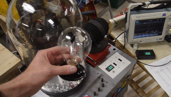
But where’s the challenge? That seems to be the question [dereksgc] asked and answered by tapping into S-band telemetry from an obsolete satellite. Most satellite hunters focus on downlinks in the L-band or even the VHF portion of the spectrum, which are within easy reach of most RTL-SDR dongles. However, the Coriolis satellite, which was launched in 2003, has a downlink firmly in the S-band, which at 2.2-GHz puts it just outside the high end of an RTL-SDR. To work around this, [dereksgc] bought a knock-off HackRF SDR and couple it with a wideband low-noise amplifier (LNA) of his own design. The dish antenna is also homebrewed from a used 1.8-m dish and a custom helical antenna for the right-hand circular polarized downlink signal.

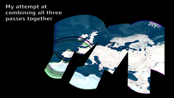
As the video below shows, receiving downlink signals from Coriolis with the rig wasn’t all that difficult. Even with manually steering the dish, [dereksgc] was able to record a couple of decent passes with SDR#. Making sense of the data from WINDSAT, a passive microwave polarimetric radiometer that’s the main instrument that’s still working on the satellite, was another matter. Decoded with SatDump and massaged with Gimp, the microwave images of Europe are at least recognizable, mostly due to Italy’s distinctive shape.

Despite the distortion, seeing the planet’s surface via the microwaves emitted by water vapor is still pretty cool. If more traditional weather satellite images are what you’re looking for, those are pretty cool too.

Continue reading “Using An Old Satellite To See The Earth In A New Light”

[Ben Krasnow] Shows Us How A Crookes Radiometer Works

[Ben Krasnow] is tackling the curious Crookes Radiometer on his Applied Science YouTube channel. The Crookes Radiometer, a staple of museum gift shops everywhere, is a rather simple device. A rotor with black and white vanes rotates on the head of a needle. The entire assembly is inside a glass envelope. The area inside the glass is not at a hard vacuum, nor is it filled with some strange gas. The radiometer only works when there is a partial vacuum inside.

The radiometer’s method of operation was long misunderstood. Sir William Crookes and James Clerk Maxwell both believed that the vanes moved due to the pressure of the photons hitting the vanes. If that were true though, the radiometer would spin in the opposite direction it normally does when held near a light source.  It was eventually discovered that the system is a thermodynamic one. [Ben] proves this by cooling down the radiometer’s glass with a can of freeze spray.  The radiometer immediately begins spinning backwards, with no light source present.

From there [Ben] mounts the rotor of a radiometer inside his vacuum chamber, which many will recognize as the chamber from his DIY electron microscope. As expected, the vanes don’t spin at a hard vacuum. In fact, [Ben] find the vanes spin fastest when the pressure is about 7 mTorr.

Continue reading “[Ben Krasnow] Shows Us How A Crookes Radiometer Works”

More Radiation Test Gear

This is a multifunction too for measuring radiation (translated). The measurements center around gas discharge tubes that react when ionizing particles pass through them. After reading about the counting circuit for the pair of tubes used in this handheld it’s easy to understand why these are tricky to calibrate. The handheld features a real-time clock as well as a GPS module. This way, it can not only give a readout of the radiation currently measured, but can record how much radiation exposure has accumulated over time (making this a dosimeter). An accompanying dataset records the location of the exposure. An ATmega128 drives the device, which is composed of two separate boards, a series of five navigation buttons, and a salvaged cellphone LCD for the readout. The translated page can be a bit hard to read at times, but there’s plenty of information including an abundance of schematic breakdowns with accompanying explanations of each.

This is certainly feature-rich and we think it goes way beyond the type of device that Seeed is trying to develop.

[Thanks Andrew]