radio direction finding

Where’s That Radio? A Brief History Of Direction Finding

We think of radio navigation and direction finding as something fairly modern. However, it might surprise you that direction finding is nearly as old as radio itself. In 1888, Heinrich Hertz noted that signals were strongest when in one orientation of a loop antenna and weakest 90 degrees rotated. By 1900, experimenters noted dipoles exhibit similar behavior and it wasn’t long before antennas were made to rotate to either maximize signal or locate the transmitter.

British radio direction finding truck from 1927; public domain

Of course, there is one problem. You can’t actually tell which side of the antenna is pointing to the signal with a loop or a dipole. So if the antenna is pointing north, the signal might be to the north but it could also be to the south. Still, in some cases that’s enough information.

John Stone patented a system like this in 1901. Well-known radio experimenter Lee De Forest also had a novel system in 1904. These systems all suffered from a variety of issues. At shortwave frequencies, multipath propagation can confuse the receiver and while longwave signals need very large antennas. Most of the antennas moved, but some — like one by Marconi — used multiple elements and a switch.

However, there are special cases where these limitations are acceptable. For example, when Pan Am needed to navigate airplanes over the ocean in the 1930s, Hugo Leuteritz who had worked at RCA before Pan Am, used a loop antenna at the airport to locate a transmitter on the plane. Since you knew which side of the antenna the airplane must be on, the bidirectional detection wasn’t a problem.

Continue reading “Where’s That Radio? A Brief History Of Direction Finding”

Radio Gets Ridiculous

There were plenty of great talks at this year’s Supercon, but we really liked the title of Dominic Spill’s talk: Ridiculous Radios. Let’s face it, it is one thing to make a radio or a computer or a drone the way you are supposed to. It is another thing altogether to make one out of things you shouldn’t be using. That’s [Dominic’s] approach. In a quick 30 minutes, he shows you two receivers and two transmitters. What makes them ridiculous? Consider one of the receivers. It is a software defined radio (SDR). How many bits should an SDR have? How about one bit? Ridiculous? Then you are getting the idea.

Dominic is pretty adept at taking a normal microcontroller and bending it to do strange RF things and the results are really entertaining. The breadboard SDR, for example, is a microcontroller with three components: an antenna, a diode, and a resistor. That’s it. If you missed the talk at Supercon, you can see the newly published video below, along with more highlights from Dominic’s talk.

Continue reading “Radio Gets Ridiculous”

Flush Out Car Thieves With A Key Fob Jammer Locator

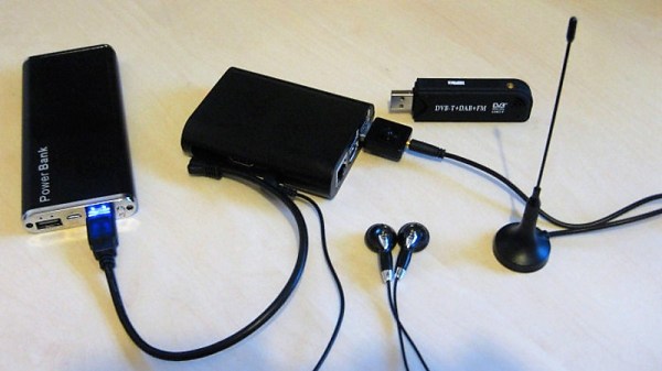
We all do it — park our cars, thumb the lock button on the key fob, and trust that our ride will be there when we get back. But there could be evildoers lurking in that parking lot, preventing you from locking up by using a powerful RF jammer. If you want to be sure your car is safe, you might want to scan the lot with a Raspberry Pi and SDR jammer range finder.

Inspired by a recent post featuring a simple jammer detector, [mikeh69] decide to build something that would provide more directional information. His jammer locator consists of an SDR dongle and a Raspberry Pi. The SDR is set to listen to the band used by key fobs for the continuous, strong emissions you’d expect from a jammer, and the Pi generates a tone that varies relative to signal strength. In theory you could walk through a parking lot until you get the strongest signal and locate the bad guys. We can’t say we’d recommend confronting anyone based on this information, but at least you’d know your car is at risk.

We’d venture a guess that a directional antenna would make the search much easier than the whip shown. In that case, brushing up on Yagi-Uda antenna basics might be a good idea.

Simple Scanner Finds The Best WiFi Signal

Want to know which way to point your WiFi antenna to get the best signal? It’s a guessing game for most of us, but a quick build of a scanning WiFi antenna using mostly off-the-shelf components could point you in the right direction.

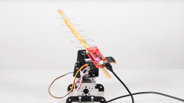
With saturation WiFi coverage in most places these days, optimizing your signal might seem like a pointless exercise. And indeed it seems [shawnhymel] built this more for fun than for practical reasons. Still, we can see applications where a scanning Yagi-Uda antenna would come in handy. The build started with a “WiFi divining rod” [shawnhymel] created from a simple homebrew Yagi-Uda and an ESP8266 to display the received signal strength indication (RSSI) from a specific access point. Tired of manually moving the popsicle stick and paperclip antenna, he built a two-axis scanner to swing the antenna through a complete hemisphere.

The RSSI for each point is recorded, and when the scan is complete, the antenna swings back to the strongest point. Given the antenna’s less-than-perfect directionality — [shawnhymel] traded narrow beam width for gain — we imagine the “strongest point” is somewhat subjective, but with a better antenna this could be a handy tool for site surveys, automated radio direction finding, or just mapping the RF environment of your neighborhood.

Yagi-Uda antennas and WiFi are no strangers to each other, whether it be a WiFi sniper rifle or another recycling bin Yagi.  Of course this scanner isn’t limited to WiFi. Maybe scanning a lightweight Yagi for the 2-meter band would be a great way to lock onto the local Ham repeater.

Continue reading “Simple Scanner Finds The Best WiFi Signal”

Tape Measure VHF Yagi Antenna

tap measure yagi vhf antenna

Radio direction finding and fox hunting can be great fun and is a popular activity with amateur radio (ham radio) enthusiasts. These antennas are great and are not only good for finding transmitters but also will greatly increase directional distance performance including communicating with satellites and the international space station (ISS).

[jcoman] had a nephew who was interested in learning about amateur radio so [jcoman] figured building and using a cheap and portable 2 meter band VHF Yagi style beam antenna would be the perfect activity to captivate the young lad’s interest in the hobby.

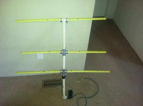
His design is based on [Joe Leggio’s] (WB2HOL) design with some of his own calculated alterations. We have seen DIY Yagi antenna designs before but what makes this construction so interesting is that the elements come together using bits of cut metal tape measure sections. These tape measure sections allow the Yagi antenna, which is normally a large and cumbersome device, to be easily stowed in a vehicle or backpack. When the antenna is needed, the tape measure sections naturally unfold and function extremely well with a 7 dB directional gain and can be adjusted to get a 1:1 SWR at any desired 2 m frequency.

The other unique feature is that the antenna can be constructed for under $20 if you actually purchase the materials. The cost would be even less if you salvage an old tape measure. You might even have the PVC pipes, hose clamps and wire lying around making the construction nearly free.

We were quite surprised to find that such a popular antenna construction method using tape measure elements had not yet been featured on Hackaday. For completeness this is not the only DIY tape measure Yagi on Instructables so also check out [FN64’s] 2 m band “Radio Direction Finding Antenna for VHF” and [manuka’s] 70 cm band “433 MHz tape measure UHF antenna” postings. The other Yagi antenna designs featured on Hackaday were “Building a Yagi Uda Antenna” and “Turning an Easter Egg Hunt into a Fox Hunt” but these designs were not so simple to construct nor as cleverly portable.