Why Is My 470uF Electrolytic Cap More Like 20uF?

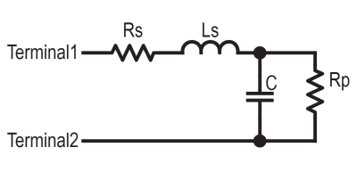
The simple capacitor equivalent circuit taught in school

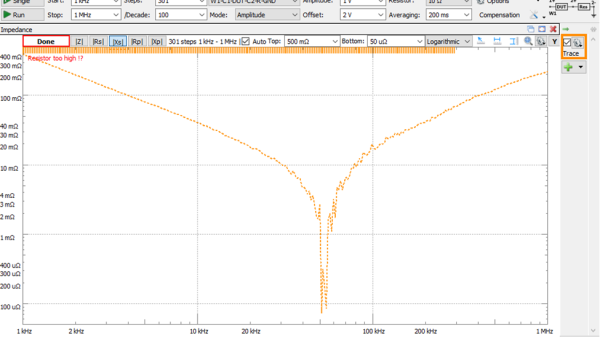
Inductors are more like a resistor in series with an ideal inductor, resistors can be inductors as well, and well, capacitors aren’t just simply a capacitance in a package. Little with electronics is as plain and simple in reality as basic theory would have you believe. [Tahmid Mahbub] was measuring an electrolytic capacitor with an LCR and noticed it measuring 19 uF despite the device being rated at 470 uF. This was because such parts are usually specified at low frequencies, and at a mere 100 kHz, it was measuring way out of the specification they were expecting. [Tahmid] goes into a fair bit of detail regarding how to model the equivalent circuit of a typical electrolytic capacitor and how to determine with a bit more accuracy what to expect.
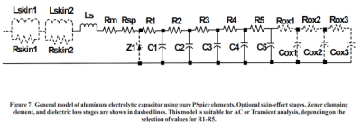
An aluminium electrolytic capacitor is more like this

The basic equivalent circuit for a capacitor has a series resistance and inductance, which covers the connecting leads and any internal tabs on the plates. A large-valued parallel resistor models the leakage through the dielectric in series with the ideal capacitance, which is responsible for the capacitor’s self-discharge property. However, this model is still too simple for some use cases. A more interesting model, shown to the left, comprises a ladder of distributed capacitances and associated resistances that result in a progressively longer time-constant component as you move from C1 to C5. This resembles more closely the linear structure of the capacitor, with its rolled-up construction. This model is hard to use in any practical sense due to the need to determine values for the components from a physical part. Still, it is useful to understand why such capacitors perform far worse than you would expect from just a simple equivalent model that looks at the connecting leads and little else.

Continue reading “Why Is My 470uF Electrolytic Cap More Like 20uF?”

Cascade Failures, Computer Problems, And Ohms Law: Understanding The Northeast Blackout Of 2003

We’ve all experienced power outages of some kind, be it a breaker tripping at an inconvenient time to a storm causing a lack of separation between a tree and a power line. The impact is generally localized and rarely is there a loss of life, though it can happen. But in the video below the break, [Grady] of Practical Engineering breaks down the Northeast Blackout of 2003, the largest power failure ever experienced in North America. Power was out for days in some cases, and almost 100 deaths were attributed to the loss of electricity.

[Grady] goes into a good amount of detail regarding the monitoring systems, software simulation, and contingency planning that goes into operating a large scale power grid. The video explains how inductive loads cause reactance and how the effect exacerbated an already complex problem. Don’t know what inductive loads and reactance are? That’s okay, the video explains it quite well, and it gives an excellent basis for understanding AC electronics and even RF electronic theories surrounding inductance, capacitance, and reactance.

So, what caused the actual outage? The complex cascade failure is explained step by step, and the video is certainly worth the watch, even if you’re already familiar with the event.

It would be irresponsible to bring up the 2003 outage without talking about the Texas ERCOT outages just one year ago– an article whose comments section nearly caused a blackout at the Hackaday Data Center!

Continue reading “Cascade Failures, Computer Problems, And Ohms Law: Understanding The Northeast Blackout Of 2003”

Otis Boykin’s Precision Passives Propelled The Pacemaker

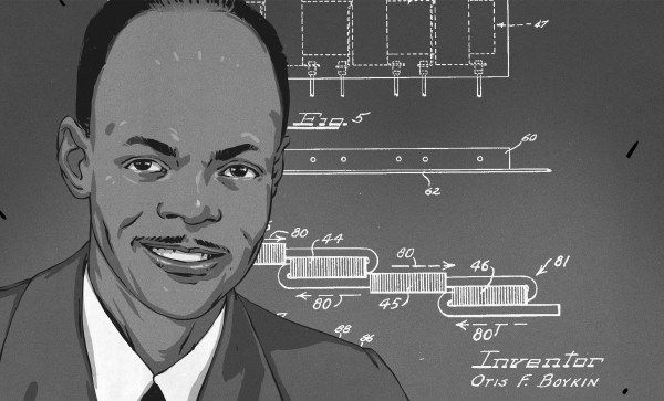
The simplest ideas can be the ones that change the world. For Otis Boykin, it was a new way to make wirewound precision resistors. Just like that, he altered the course of electronics with his ideas about what a resistor could be. Now his inventions are in everything from household appliances and electronics to missile guidance computers.

While we like to geek out about developments in resistor tech, Otis’ most widely notable contribution to electronics is the control unit he designed for pacemakers, which regulate a person’s heartbeat. Pacemakers are a real-time clock for humans, and he made them more precise than ever.

Street Smarts and Book Smarts

Otis Frank Boykin was born August 29th, 1920 in Dallas, Texas to Sarah and Walter Boykin. Otis’ father was a carpenter who later became a preacher. His mother Sarah was a maid, and she died of heart failure when Otis was only a year old.

Continue reading “Otis Boykin’s Precision Passives Propelled The Pacemaker”

Mains Power Supply For ATtiny Project Is Probably A Bad Idea

When designing a mains power supply for a small load DC circuit, there are plenty of considerations. Small size, efficiency, and cost of materials all spring to mind. Potential lethality seems like it would be a bad thing to design in, but that didn’t stop [Great Scott!] from exploring capacitive drop power supplies. You know, for science.

The backstory here is that [Great Scott!] is working on a super-secret ATtiny project that needs to be powered off mains. Switching power supplies are practically de rigueur for such applications, but compared to the intended microcontroller circuit they are actually quite large, and they’ve just been so done before. So in order to learn a thing or two, [Scott!] designed a capacitive dropper supply, where the reactance of the cap acts like a dropping resistor to limit the current. His first try was just a capacitor in series with an LED; this didn’t end well for the LED.

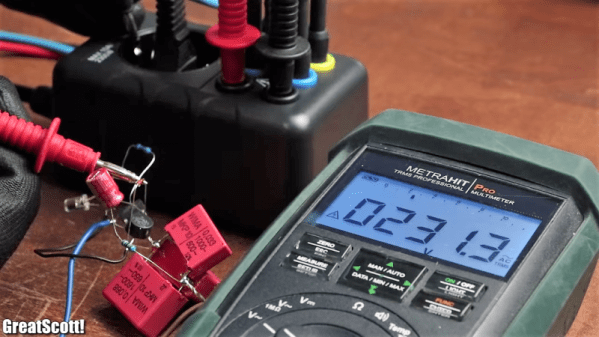
To understand why, he reverse-engineered a few low-current mains devices and found that practical capacitive droppers need a few more components, chiefly a series resistance to prevent inrush current from getting out of hand, but also a bridge rectifier and a zener to clamp things down. Wiring up all that resulted in a working capacitive dropper supply, but a the cost of as much real estate as a small switcher, and with the extra bonus of being potentially lethal if the power supply is plugged in the wrong way. Side note: we thought German line cords were polarized to prevent this, but apparently not? (Ed Note: Nope!)

As always, even when [Great Scott!]’s projects don’t exactly work out, like a suboptimal 3D-printed BLDC or why not to bother building your own DC-AC inverter, we enjoy the learning that results.

Continue reading “Mains Power Supply For ATtiny Project Is Probably A Bad Idea”

Sign Of The Smith Chart Times

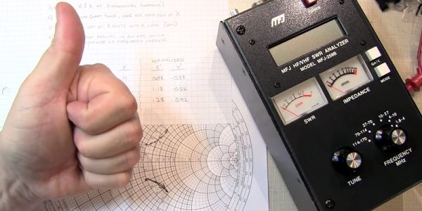
The Smith chart is a staple for analyzing complex impedance. [W2AEW] notes that a lot of inexpensive test gear like the MFJ-259B gives you complex readings, but fails to provide the sign of the imaginary part of the complex number. That makes it difficult to plot the results on a Smith chart or carry out other analysis. As you might expect, though, he has a solution for you that you can see in the video, below.

A common method is to increase the frequency slightly. In a simple case, you’d expect the imaginary part — the reactance — to go down for a capacitive impedance and up for an inductive one. Unfortunately, this doesn’t apply in many common cases, including when you are measuring through a transmission line which is probably what most people are doing with this type of test gear.

Continue reading “Sign Of The Smith Chart Times”

The Beginnings Of An LCR Meter

LCR Meter

The inductor is an often forgotten passive electrical elements used to design analog circuitry. [Charles’s] latest proof of concept demonstrates how to measure inductance with an oscilloscope, with the hopes of making a PIC based LCR meter.

It is not that often one needs to measure inductance, but inductors are used in switching regulators, motor circuits, wireless designs, analog audio circuitry, and many other types of projects. The principles of measuring inductance can be used to test inductors that you have made yourself, and you can even use this knowledge to measure capacitance.

[Charles] originally saw a great guide on how to measure impedance by [Alan], and decided to run with the idea. Why spend over $200 on an LCR meter when you can just build one? That’s the spirit! Be sure to watch [Alan’s] and [Charles’s] videos after the break. What kind of test equipment have you built in order to save money?

Continue reading “The Beginnings Of An LCR Meter”