[Uri Shaked] accidentally touched a GPIO pin on his 3.3 V board with a 12 V alligator clip, frying the board. Sound familiar? A replacement would have cost $60, which for him wasn’t cheap. Also, he needed it for an upcoming conference so time was of the essence. His only option was to try to fix it, which in the end involved a delicate chip transplant.
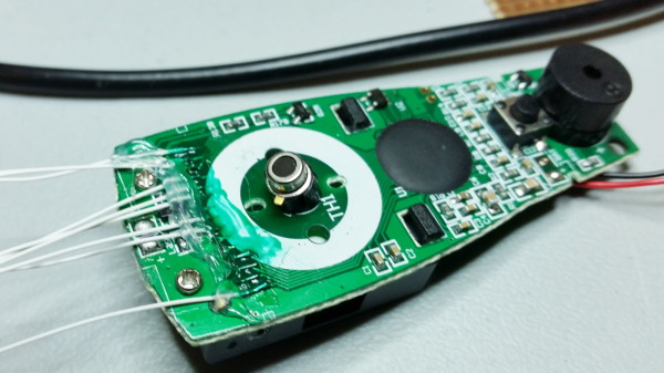
 The board was the Pixl.js, an LCD board with the nRF52832 SoC with its ARM Cortex M4, RAM, flash, and Bluetooth LE. It also has a pre-installed Espruino JavaScript interpreter and of course the GPIO pins through which the damage was done.
Fortunately, he had the good instinct to feel the metal shield over the nRF52832 immediately after the event. It was hot. Applying 3.3 V to the board now also heated up the chip, confirming for him that the chip was short-circuiting. All he had to do was replace it.
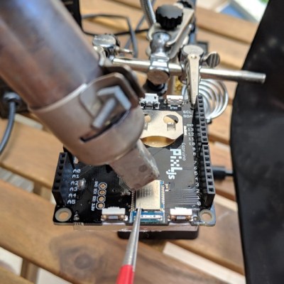
Digging around, he found another nRF52832 on a different board. To our surprise, transplanting it and getting the board up and running again took only an hour, including the time to document it. If that sounds simple, it was only in the way that a skilled person makes something seem simple. It included plenty of delicate heat gun work, some soldering iron microsurgery, and persistence with a JLink debugger. But we’ll leave the details of the operation and its complications to his blog. You can see one of the steps in the video below.
It’s no surprise that [Uri] was able to dig up another board with the same nRF52832 chip. It’s a popular SoC, being used in tiny, pocket-sized robots, conference badges, and the Primo Core board along with a variety of other sensors.
Continue reading “Performing A Chip Transplant To Resurrect A Dead Board”