fiber matrix

Big LED Matrix Becomes Tiny LED Matrix Thanks To Fiber Optics

Everyone loves LED matrices, and even if you can’t find what you like commercially, it’s pretty easy to make just what you want. Need it big? No problem; just order a big PCB and some WS2812s. Need something tiny? There are ridiculously small LEDs that will test your SMD skills, as well as your vision.

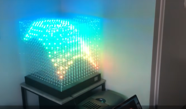
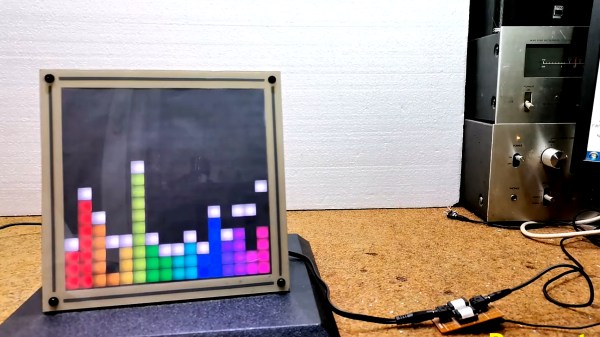
But what if you want a small matrix that’s actually a big matrix in disguise? For that, you’ll want to follow [elliotmade]’s lead and incorporate fiber optics into your LED matrix. The build starts with a 16×16 matrix of WS2812B addressable LEDs, with fairly tight spacing but still 160 mm on a side. The flexible matrix was sandwiched between a metal backing plate and a plastic bezel with holes directly over each LED. Each hole accepts one end of a generous length of flexible 1.5-mm acrylic light pipe material; the other end plugs into a block of aluminum with a 35 by 7 matrix of similar holes. The small block is supported above the baseplate by standoffs, but it looks like the graceful bundle of fibers is holding up the smaller display.

A Raspberry Pi Pico running a CircutPython program does the job of controlling the LEDs, and as you can see in the video below, the effect is quite lovely. Just enough light leaks out from the fibers to make a fascinating show in the background while the small display does its thing. We’ve seen a few practical uses for such a thing, but we’re OK with this just being pretty. It does give one ideas about adding fiber optics to circuit sculptures, though.

Continue reading “Big LED Matrix Becomes Tiny LED Matrix Thanks To Fiber Optics”

Tileable LED matrix

Tiny LED Matrix Panels Tile Together Perfectly

There’s a lot to admire about LED matrix projects, which more often than not end up looking really cool. But most of them rely on RGB matrix panels sourced from the surplus market, and while there’s nothing wrong with that, building your own tiny, tileable LED matrix panels makes these builds just a little bit cooler.

There’s a lot to admire about these matrix panels, not least of which is the seamless way they tile together. But to get to that point, [sjm4306] had a lot of prep work to do. He started with a much simpler 5×7 array, using the popular WS2812 RGB LEDs on a custom PCB. With a little practice under his belt, it was time to move to the much smaller SK6805 LEDs, which were laid out in an 8×8 matrix. The board layout is about as compact as it can be; [sjm4306] reports that it pushed the PCB fab to their limits, but he ended up with LEDs spaced perfectly on the board and just enough margin to keep consistent spacing in two dimensions when the boards are adjacent to each other.

Assembly of the boards was challenging, to say the least. The video below shows that the design left barely enough room for handling the LEDs with tweezers, and some fancy finagling was needed to get the boards on and off the hotplate for reflow. [sjm4306] says that he’ll be exploring JLC PCB’s assembly service in the future, since each board took an hour for him to assemble. But they look fantastic when daisy-chained together, with no detectable gaps at the joints.

With matrices like these, the possibilities are endless. We’ve even got a whole list of LED matrix projects over on Hackaday.io for you to check out.

Continue reading “Tiny LED Matrix Panels Tile Together Perfectly”

3D printed moon lamp

3D Printed Lithographic Moon Lamp

After years of being a software developer, [Chris] was excited to get back into embedded development and we’re glad he did. His 3D printed lithographic moon lamp combines a number of hacker and maker skills, and is sure to impress.

3D-printed lithographic moons have gotten pretty popular these days, so he was able to find a suitable model on Thingiverse to start with. Gotta love open-source. Of course, he needed to make a few modifications to fit his end design. Namely, he put a hole at the bottom of the moon, so he could slide the LED and heatsink inside. The 3 watt LED is pretty beefy, so he definitely needed a heat sink to make sure everything stayed cool.

Otherwise, the circuit itself is pretty straightforward. He has an ESP32 to drive the RGB LED through a transistor, and fitted the components onto a custom-designed circuit board to ensure everything stayed neat and organized. You don’t want a ton of loose wires and breadboards cluttering this build. Since he used an ESP32, he was able to create a simple web interface to control the color of the LEDs. Gotta make it connected somehow, right?

What’s great is in addition to the project write-up, [Chris] includes video tutorials, walking the readers through each individual step of the build. By doing so he really makes it easy for readers to follow along and reuse his work. If you’re still looking for ideas, one of these could make a really good Christmas present.

Continue reading “3D Printed Lithographic Moon Lamp”

Slick Keyboard Built With PCB Magic

Sometimes a chance conversation leads you to discover something cool you’ve not seen before, and before you know it, you’re ordering parts for yet another hardware build. That’s what happened to this scribe the other day when chatting on some random discord, to QMK maintainer [Nick Brassel aka tzarc] about Djinn, a gorgeous 64-key split mechanical keyboard testbed. It’s a testbed because it uses the newest STM32G4x microcontroller family, and QMK currently does not have support for this in the mainline release. For the time being, [Nick] maintains a custom release, until it gets merged.

Hardware-wise, the design is fabulous, with a lot of attention to detail. We have individual per-key RGB LEDs, RGB underglow, a rotary encoder, a five-way tactile thumb switch, and a 240×320 LCD per half. The keyboard is based on a three PCB stack, two of which are there purely for structure. This slick design has enough features to keep a fair few of us happy.

Interestingly, when you look at the design files (KiCAD, naturally) [Nick] has chosen to take a mirrored approach to the PCB. That means the left and right sides are actually the same PCB layout. The components are populated on different sides of the PCB depending on which half you’re looking at! By mirroring footprints on both PCB sides, and hooking everything up in parallel, it’s possible to do it all with a single master layout.

This is a simple but genius idea that this scribe hadn’t come across before (the shame!) Secondarily it keeps costs down, as your typical Chinese prototyping house will not deal in PCB quantities below five, so you can make two complete keyboards on one order, rather than needing two orders to make five. (Yes, there are actually three unique PCBs, but we’re simplifying the situation, ok?)

Now, if only this pesky electronics shortage could abate a bit, and we could get the parts to build this beauty!

Obviously, we’ve covered many, many keyboards over the years. Here’s our own [Kristina’s] column all about the things. If you need a little help with your typing skills, this shocking example may be the one for you. If your taste is proper old-school clackers, there’s something for everyone.

Big RGB LED Cube You Can Build Too

LED cubes are really nothing new, many of us consider the building of a good sized one almost an electronics rite of passage that not so many manage to find the time or have the skill to pull off. It’s our pleasure to draw your attention to a lovely build, showing all the processes involved, the problems and the solutions found along the way.

Building a small cube is somewhat of a trivial affair, especially without considering PWM colour mixing, however as simple maths will illustrate, as you increase the number of LEDs on each side, the total number will quickly get quite large. More LEDs need more power and increase control complexity considerably. A larger matrix like this 16 x 16 x 16 LED build, has a total of 4096. This would be a nightmare to drive with plain RGB LEDs, even with cunning multiplexing, but luckily you can buy indexable LEDs in a through-hole package similar to the ubiquitous WS2812-based SMT LEDs you see around. These are based on the PD9823 controller, which can be programmed as if they were a WS2812, at least according to this analysis. Now you can simply chain a column of LEDs, with the control signal passed from LED to nearest neighbour.

Early on in the video build log, you will note there are four power supply modules needed to feed this juice. If we assume each LED consumes 60 mA on full-white (the data for this product link shows a peak value of 100 mA) that is still a total of 246 A or around 1 kW of power. The video does shows a peak power measurement of around this figure, for the whole array on full white, so the maths seems about right.

Control is via a Teensy 4.0 using the FlexIO function of the IMXRT1060RM CPU, and a bunch of 74AHCT595 shift registers giving 32 channels of up to 1000 LEDs per channel if needed. Roughly speaking, using the DMA with FlexIO, the Teensy can drive up to 1 Million LED updates per second, which works out about 32 channels of 100 LEDs per channel updated at 330 frames/sec, so plenty of resource is available. All this is with almost no CPU intervention, freeing that up for handling the 2.4-inch LCD based UI and running the animations, which looks pretty darn slick if you ask us. You can checkout the description of the firmware in the firmware section of the GitHub project. 3D printed jigs allowed for bending and clipping the LEDs leads as well as fixing and aligning the LED column units, so there really is enough detail there to allow anyone so inclined reproduce this, so long as you can swallow the cost of all those LEDs.

For a different approach to LED cubes, checkout this sweet panel based approach, and here’s a really small 4x4x4 module for those with less space to spare.

Continue reading “Big RGB LED Cube You Can Build Too”

FFT display on 16x16 RGB LED grid

Art Project Fast And Fouriously Transforms Audio Into Eye Candy

Fast Fourier Transforms. Spectrum Analyzers. Waterfall displays. Not long ago, such terms were reserved for high end test gear. But oh, how things have changed! It’s no surprise to many Hackaday readers that modern microcontrollers have transformed the scene as they become more powerful and as a result are endowed with more and more powerful software libraries. [mircemk] has used such a library along with other open source software combined with mostly off the shelf hardware to create what he calls the DIY FFT Spectrum Analyzer. Rather than being a piece of test gear, this artful project aims to please the eye.

The overall build is relatively simple. Audio is acquired via a line-in jack or a microphone, and then piped into an ESP32. The ESP32 runs the audio through the FFT routine, sampling, slicing, and dicing the audio into 16 individual bands. The visual output is displayed on a 16 x 16 WS2812 Led Matrix. [mircemk] wrote several routines for displaying the incoming audio, with a waterfall, a graph, and other visualizations that are quit aesthetically pleasing. Some of them are downright mesmerizing! You can see the results in the video below the break.

Of course the build doesn’t stop with slapping some hardware and a few passive components together. To really be finished, it needs to be encased in something worth displaying. [mircemk] does not disappoint, as a beautiful 3D-printed enclosure wraps it all up nicely.

We think that the final product is great, and it reminds us of some of the very things that inspired us early on in our hacking careers. We would love to see this project integrated with an Interactive Musical Art Installation of any kind, the more esoteric the better. Perhaps a 555 timer synth could fit the bill? Be sure to share your own hacks with us via the Tip Line!

Continue reading “Art Project Fast And Fouriously Transforms Audio Into Eye Candy”

A Perfect Clock For Any Hacker’s Ohm

The vast majority of us are satisfied with a standard, base ten display for representing time. Fewer of us like to be a bit old-fashioned and use a dial with a couple of hands that indicate the time, modulo twelve. And an even smaller minority, with a true love for the esoteric, are a fan of binary readouts. Well, there’s a new time-telling game in town, and as far as we’re concerned it’s one of the best ones yet: resistor color codes.

The Ohm Clock is, as you may have guessed, a giant model of a resistor that uses its color bands to represent time.  
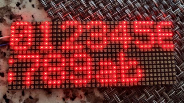
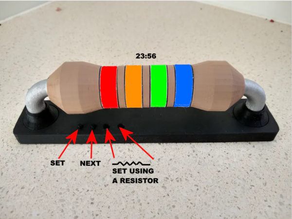
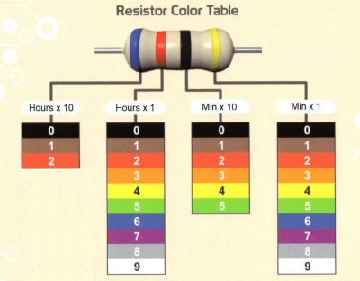
Each of the four bands represents a digit in the standard HH:MM representation of time, and for anybody well-versed in resistor codes this is sure to be a breeze to read. The clock itself was designed by [John Bradnam]. It’s body is 3D printed, with RGB LEDs to brightly illuminate each segment. The whole thing is controlled by an old favorite – an ATtiny, supported by a Real Time Clock (RTC) chip for accurate timekeeping.

You can set the time in the traditional fashion using buttons, or — and here’s the brilliant part — you can use a resistor. Yup, that’s right. Connecting a 220 Ohm resistor across two terminals on the clock will set the time to 2:20. Genius.

When you come across an art as old as timekeeping, it’s easy to assume that everything’s already been done. We have sundials, hourglasses, analog clocks, digital watches, those cool clocks that use words instead of numbers, the list goes on. That’s why it’s so exciting to see a new (and fun!) idea like this one emerge.