Create Your RTL Simulations With KiCAD

[Bob Alexander] is in the process of designing a homebrew discrete TTL CPU, and wanted a way to enter schematics for digital simulations via a Verilog RTL flow. Since KiCAD is pretty good at handling hierarchical schematics, why not use that? [Bob] created a KiCAD plugin, KiCadVerilog allowing one to instantiate and wire up the circuits under consideration, and then throw the resulting Verilog file at your logic simulator of choice.

KiCadVerilog doesn’t do all the hard work though, as it only provides the structure and the wiring of the circuit. The actual guts of each TTL instance needs to be provided, and a reference to it is manually added to the schematic object fields. That’s a one-time deal, as you can re-use the component library once generated. Since TTL logic has been around for a little while, locating a suitable Verilog library for this is easy. Here’s ice-chips-verilog by [TimRudy] on GitHub for starters. It’s intended as a collection for Icestudio (which is also worth a look). Still, the Verilog code for many TTL series devices is presented ready for the taking, complete with individual test benches in case you need them.

Check out the project GitHub page for the module source code, and some more documentation about the design process.

We’ve seen many RTL hacks over the years, here’s an interesting way to generate a PCB layout with discrete logic, direct from the RTL.

DIY All-Transistor Addressable Pixel

By now most readers should be used to addressable LEDs, devices that when strung out in a connected chain can be individually lit or extinguished by a serial data stream. Should you peer at one under a microscope you’ll see alongside the LED dies an integrated circuit that handles all the address decoding. It’s likely to be quite a complex device, but how simply can its functions be replicated? It’s a theme [Tim] has explored in the TransistorPixel, and addressable LED board that achieves addressability with only 17 transistors.

It uses a surprisingly straightforward protocol, in which a pulse longer than 500ns enables the LED while a shorter one turns it off. Subsequent pulses in a train are passed on down the line to the next device. A 20µs absence of a pulse resets the string and sets it to wait for the next pulse train. Unlike the commercial addressable LEDS there is only a single colour and no suport for gradated brightness, but it’s still an impressive circuit.

Under the hood is some very old-school RTL logic, a monostable to detect the pulse and a selection of gates and a latch to capture the state and forward to the chain. It’s laid out on a PCB in order of circuit function, and while we can see that maybe it’s not a practical addresssable LED for 2021, it’s likely that it could be made into a much smaller PCB if desired.

Perhaps unsurprisingly given the ready availability of addressable LEDs, we’ve not seen many home made ones. This addressable 7-segment display may be the closest.

Chaotic Oscillator From Antique Logic

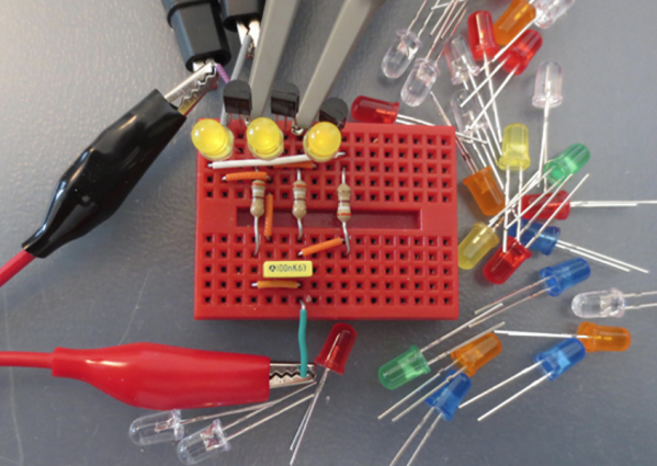
While working on recreating an “ancient” (read: 60-year-old) logic circuit type known as resistor-transistor logic, [Tim] stumbled across a circuit with an unexpected oscillation. The oscillation appeared to be random and had a wide range of frequency values. Not one to miss out on a serendipitous moment, he realized that the circuit he built could be used as a chaotic oscillator.

Chaotic systems can be used for, among other things, random number generation, so making sure that they do not repeat in a reliable way is a valuable property of a circuit. [Tim]’s design uses LEDs in series with the base of each of three transistors, with the output of each transistor feeding into the input of the next transistor in line, forming a ring. At certain voltages close to the switching voltages of the transistors, the behavior of the circuit changes unpredictably both in magnitude and frequency.

Building real-life systems that exhibit true randomness or chaotic behavior are surprisingly rare, and even things which seem random are often not random enough for certain applications. [Tim]’s design benefits from being relatively simple and inexpensive for how chaotic it behaves, and if you want to see his detailed analysis of the circuit be sure to visit his project’s page.

If you want to get your chaos the old fashioned way, with a Chua circuit, look out for counterfeit multipliers.

All The Goodies You Need For Your RTL-SDR

When the RTL2832-based USB digital TV sticks were revealed to have hidden capabilities that made the  an exceptionally cheap software-defined radio receiver, it was nothing short of a game-changing moment for the home radio experimenter. The RTL might not be the best radio available, but remains a pretty good deal for only $10 from your favourite online supplier.

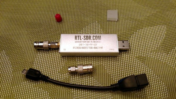
Having bought your RTL SDR, you will soon find yourself needing a few accessories. A decent antenna perhaps, an HF upconverter, and maybe an attenuator. To help you, [IgrikXD] has come up with a repository containing open-source implementations of all those projects and more. There’s an HF upconverter handily in both SMD and through-hole versions, as well as a wideband active antenna. A resonant antenna for a single band will always out-perfom a wideband device if your interest lies on only one frequency, but when your receiver has such a wide range as that of the RTL it’s irresistible to look further afield so the wideband antenna is a useful choice.

The RTL SDR is a device that just keeps on giving, and has featured innumerable times here since since its first appearance a few years ago. Whether you are into passive radar or using it to decode data from RF-equipped devices it’s the unit of choice, though we rather like it as a piece of inexpensive test equipment.

Via Hacker News.

Header image: Joeceads [CC BY-SA 4.0].

Measuring HF Signal Speeds In A DIY Coaxial Collinear Antenna

Air Traffic Controllers use Automatic Dependent Surveillance-Broadcast (ADS-B) as an alternative to secondary radar to track aircraft. The ADS-B is transmitted by the aircraft and contains information such as GPS position, pressure, altitude, and callsign among other things at a 1090 MHz frequency, which can be decoded using any of a number of software tools.

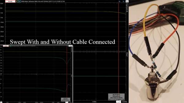
[Mike Field] lives near an airport, and decided he wanted to peek into the tracking signals for fun. He turned to an RTL-based TV Dongle. Since the stock antenna was not cutting it, he decided to make one specifically for the 1090 MHz signal. His design is based on Coaxial Collinear Antenna for ADS-B Receiver by [Dusan Balara] which uses pieces of the coaxial cable cut to the right length. There are a number of calculations involved in determining the size of the cable, however, the hack in this design is the way he uses a USB based oscilloscope to measure the speed of RF waves inside the line in question.

We reached out to [Mike], and this is what he had to say. The idea is to use a cable of half the size of the wavelength which is calculated as

lambda = c/f

For the best reception, the sections of coax need to be half a wavelength long – but the wavelength of the signal inside the coax, which is shorter than the wavelength in free space. As this was a generic cable he had no idea of the dielectric that separates the core from the shield, so the ‘velocity factor’ could be anything depending on the exact composition.

To determine the speed of the signal in the cable, his approach omits the more expensive equipment. A length of coax acts as a stub – any energy that is sent into the cable reaches the far end of the transmission line and is then reflected back to the source. When the cable is 1/4th of the wavelength long, the reflected signal arrives back at the start of the signal 180 degrees out of phase – in a perfect world it would completely null out the input signal. Continue reading “Measuring HF Signal Speeds In A DIY Coaxial Collinear Antenna”

Gates To FPGAs: TTL Electrical Properties

On the path to exploring complex logic, let’s discuss the electrical properties that digital logic signals are comprised of. While there are many types of digital signals, here we are talking about the more common voltage based single-ended signals and not the dual-conductor based differential signals.

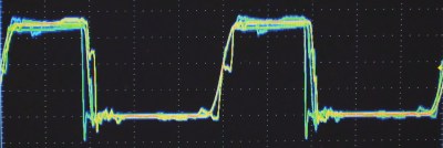
Simulated "Real Life"
Single-ended Logic Signal

I think of most logic as being in one of two major divisions as far as the technology used for today’s logic: Bipolar and CMOS. Bipolar is characterized by use of (non-insulated gate) transistors and most often associated with Transistor Transistor Logic (TTL) based logic levels. As CMOS technology came of age and got faster and became able to drive higher currents it began to augment or offer an alternative to bipolar logic families. This is especially true as power supply voltages dropped and the need for low power increased. We will talk more about CMOS in the next installment.

TTL was a result of a natural progression from the earlier Resistor Transistor Logic (RTL) and Diode Transistor Logic (DTL) technologies and the standards used by early TTL became the standard for a multitude of logic families to follow.

Continue reading “Gates To FPGAs: TTL Electrical Properties”

Measuring Filters And VSWR With RTL-SDR

Once again the ubiquitous USB TV tuner dongle has proved itself more than capable of doing far more than just receiving broadcast TV. Over on the RTL-SDR blog, there’s a tutorial covering the measurement of filter characteristics using a cheap eBay noise source and an RTL-SDR dongle.

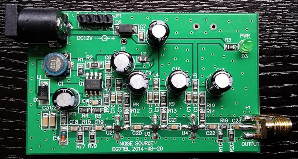
For this tutorial, the key piece of equipment is a BG7TBL noise source, acquired from the usual online retailers. With a few connectors, a filter can be plugged in between this noise source and the RTL-SDR dongle. With the hardware out of the way, the only thing remaining is the software. That’s just rtl_power and this wonderful GUI. The tutorial is using a cheap FM filter, and the resulting plot shows a clear dip between 50 and 150 MHz. Of course this isn’t very accurate; there’s no comparison to the noise source and dongle without any attenuation. That’s just a simple matter of saving some scans as .csv files and plugging some numbers in Excel.

The same hardware can be used to determine the VSWR of an antenna, replacing the filter with a directional coupler; just put the coupler between the noise source and the dongle measure the attenuation through the range of the dongle. Repeat with the antenna connected, and jump back into Excel.