New Release Of FidoCadJ Draws Schematics Everywhere

Do you remember drawing your first schematic? Presumably you used a pen or a pencil and some kind of paper. Schematic capture software, though, makes it so much easier to draw schematics. There are many to choose from, but we spent some time checking out FidoCadJ and found it capable. Of course, there are many other options, but we did like that FidoCadJ runs locally and since it uses Java will run on just about any computer. Since it is open-source, you can modify it and you don’t have to worry about licensing it for your many computers or your team.

The program is a JAR file, and our first attempt to run it ran afoul of our older Java version that was the default Java Runtime Environment. But that was easy to fix, especially since a newer version was there, just not the default.

Continue reading “New Release Of FidoCadJ Draws Schematics Everywhere”

Reverse Engineering A Saab’s In-Dash Display

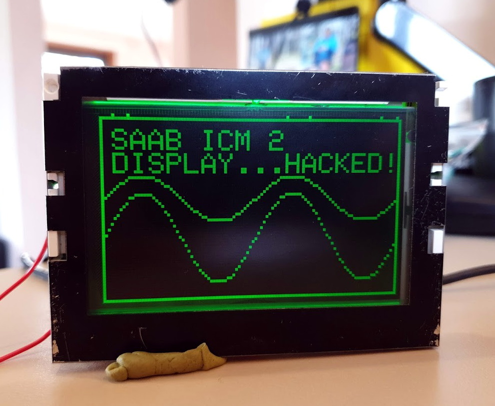
For [Leigh Oliver], there’s something undeniably appealing about the green on black instrumentation of the 2003 Saab 9-3 Gen2. Perhaps it’s because the Infotainment Control Module 2 (ICM2) screen brings a bit of that classic Matrix vibe to the daily commute. Whatever the reason, it seemed the display deserved better than to be stuck showing the nearly 20 year old stock user interface. Luckily, you can control it via I2C.

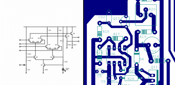
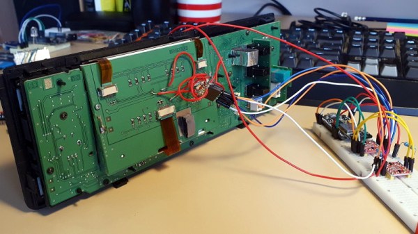
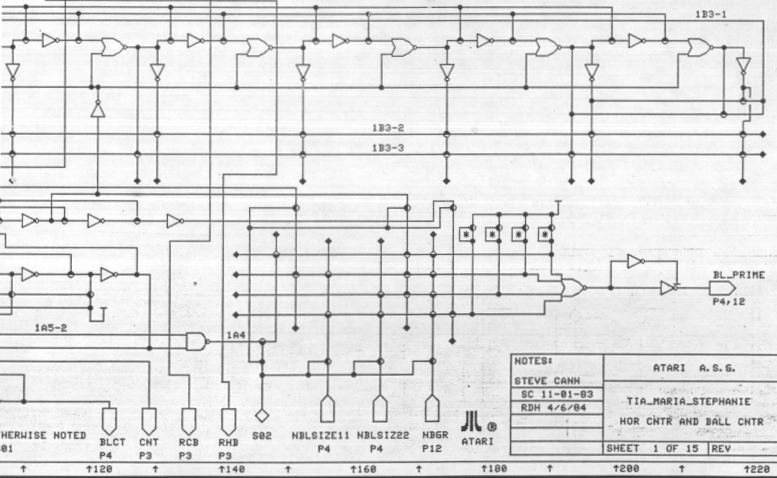
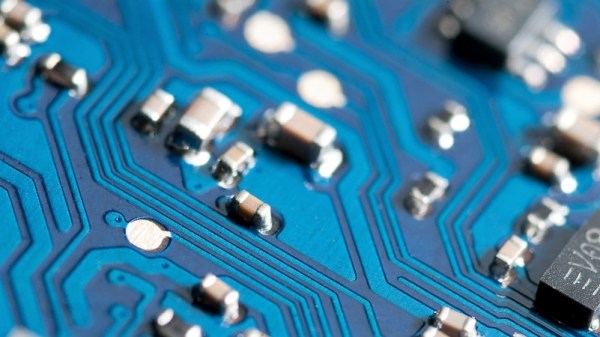
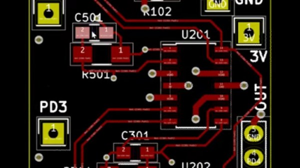
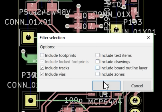
Though as you might expect, that fact wasn’t obvious at first. [Leigh] had to start by taking the ICM2 apart and reverse engineering the display board. With a multimeter and high resolution photographs of both sides of the PCB, all of the traces were mapped out and recreated in KiCAD. This might not have been strictly necessary, but it did serve as good practice for using KiCAD; a worthwhile tip for anyone else looking to build practical experience creating schematics.

With everything mapped out, [Leigh] was able to connect a BusPirate V3 up to the board and pretty quickly determine it was using I2C to control the display. As far as figuring out how to repurpose existing displays goes, this was perhaps the best possible scenario. It even allowed for creating a display library based on Adafruit_GFX which offers graphical capabilities far beyond what the ICM2 module itself is capable of.

Even with so much progress made, this project is really just getting started. [Leigh] has managed to put some impressive imagery on the black and green Saab display, but the hardware side of things is still being worked on. For example, there’s some hope that an I2C multiplexer would allow the display to easily and quickly be switched between “stock” mode and whatever enhanced version comes about thanks to the new libraries and an ESP8266 hiding behind the dashboard.

If you don’t have a sufficiently vintage Saab to take advantage of this project, don’t worry. Tapping into the OBD port with an OLED display can get you similar results on a wide range of vehicles.

An Atari Graphics Chip, Ready For You To Build

The most notable of the home computer and console hardware from the 8-bit golden era didn’t get their impressive sound and graphics from off-the-shelf silicon, instead they relied on secretive custom chipsets to get the edge over their competitors. Unfortunately for vintage gaming aficionados, those chips are now long out of production and in many cases there’s little information to be had about their operation.

Which makes discovery of the schematics (PDF link) for the “Tia Maria” graphics chip found in the Atari 7800 console an unusual occurrence, and one which should be of special interest to the emulation community. They can be found alongside the rest of the Atari Museum’s 7800 information.

That such a useful document is available at all is due to a lucky find in a dumpster following the demise of Atari, when a treasure trove of documents was discarded. It seems that the existence of these schematics has been known within the Atari community for some time, and we expect before long this information will find its way into FPGA implementations of the 7800; especially since the system features nearly complete backwards compatibility with the massively successful Atari 2600.

When that happens we hope we’ll be able to bring it to you, but it’s not the first time someone’s made an Atari on an FPGA.

Via RetroRGB

Header image: Bilby [CC BY 3.0]

EasyEDA Hack Chat With Dillon He

Join us Wednesday at 5:00 PM Pacific time for the Easy EDA Hack Chat with Dillon He!

Note the different time than our usual Hack Chat slot! Dillon will be joining us from China.

Since the birth of electronic design automation in the 1980s, the universe of products to choose from has grown tremendously. Features from schematic editing to circuit simulation to PCB design and autorouting can be found in every permutation imaginable, and you’re sure to find something that fits your needs, suits your budget, and works on your platform.

Dillon He started EasyEDA back in 2010 with Eric Cui, and since then the cloud-based EDA tool has become a popular choice. From working across teams to its “run anywhere” capabilities, EasyEDA has become the go-to tool for hundred of thousands of designers. Dillon will drop by the Hack Chat to answer all your questions about EasyEDA — how it started, where it is now, and what we can expect in the future.

join-hack-chatOur Hack Chats are live community events in the Hackaday.io Hack Chat group messaging. This week we’ll be sitting down on Wednesday, June 19 at 5:00 PM Pacific time. If time zones have got you down, we have a handy time zone converter.

Click that speech bubble to the right, and you’ll be taken directly to the Hack Chat group on Hackaday.io. You don’t have to wait until Wednesday; join whenever you want and you can see what the community is talking about.


KiCad And FreeCAD Hack Chat

Join us Wednesday at noon Pacific time for the KiCad and FreeCAD Hack Chat led by Anool Mahidharia!

The inaugural KiCon conference is kicking off this Friday in Chicago, and KiCad aficionados from all over the world are gathering to discuss anything and everything about the cross-platform, open-source electronic design automation platform. As you’d expect, Hackaday will have a presence at the conference, including a meet and greet after party. There’ll also be talks by a couple of our writers, including Anool Mahidharia, who’ll be taking time out of his trip to the States to drop by the Hack Chat with a preview of his talk, entitled “Fast 3D Model Creation with FreeCAD”.

Join us for the KiCad and FreeCAD Hack Chat this week with your questions about KiCad and FreeCAD. If you’ve got some expertise with electronic design tools, make sure you come by and contribute to the discussion too — we’d love to hear your insights. And as always, you can get your questions queued up by leaving a comment on the KiCad and FreeCAD Hack Chat event page and we’ll put them on the list for the Hack Chat discussion.

join-hack-chatOur Hack Chats are live community events in the Hackaday.io Hack Chat group messaging. This week we’ll be sitting down on Wednesday, April 24, at noon, Pacific time. If time zones have got you down, we have a handy time zone converter.

Click that speech bubble to the right, and you’ll be taken directly to the Hack Chat group on Hackaday.io. You don’t have to wait until Wednesday; join whenever you want and you can see what the community is talking about.

Byte Sized Pieces Help The KiCad Go Down

It’s no surprise that we here at Hackaday are big fans of Fritzing KiCad. But to a beginner (or a seasoned veteran!) the learning curve can be cliff-like in its severity. In 2016 we published a piece linking to project by friend-of-the-Hackaday [Chris Gammell] called Contextual Electronics, his project to produce formalized KiCad training. Since then the premier “Getting to Blinky” video series has become an easy recommendation for anyone looking to get started with Libre EDA. After a bit of a hiatus [Chris] is back with bite sized videos exploring every corner of the KiCad-o-verse.

A Happy [Chris] comes free with every video
The original Getting to Blinky series is a set of 10 videos up to 30 minutes long that walks through everything from setting up the the KiCad interface through soldering together some perfect purple PCBs. They’re exhaustive in coverage and a great learning resource, but it’s mentally and logistically difficult to sit down and watch hours of content. Lately [Chris] has taken a new tack by producing shorter 5 to 10 minute snapshots of individual KiCad features and capabilities. We’ve enjoyed the ensuing wave of learning in our Youtube recommendations ever since!

Selecting traces to rip up

Some of the videos seem simple but are extremely useful. Like this one on finding those final disconnected connections in the ratsnest. Not quite coverage of a major new feature, but a topic near and dear to any layout engineer’s heart. Here’s another great tip about pulling reference images into your schematics to make life easier. A fantastic wrapped up in a tidy three minute video. How many ways do you think you can move parts and measure distances in the layout editor? Chris covers a bunch we hadn’t seen before, even after years using KiCad! We learned just as much in his coverage of how to rip up routed tracks. You get the idea.

We could summarize the Youtube channel, but we aren’t paid by the character. Head on down to the channel and find something to learn. Make sure to send [Chris] tips on content you want him to produce!

Ask Hackaday: How Do You Draw Schematics?

The lingua franca of electronic design is the schematic. I can pick up a datasheet written in Chinese (a language I do not read or speak) and usually get a half-decent idea of what the part is all about from the drawings. Unfortunately, even as my design experience has grown over the years, I haven’t quite learned to think in schematics — I need to see it on paper (or on a screen) to analyze a circuit. Whether it’s literally on the back of an envelope or sketched in the condensation on the shower stall, actually drawing a design or idea makes a huge difference in being able to understand it. And, if you’ve ever tried to explain a circuit without a schematic — in an on-line forum or over the phone, for instance — you know how difficult it is.

So, given the importance of the schematic for design and communication, you’d think choosing a tool to draw them would be an easy task. Not so. There are dozens of choices, from dedicated schematic drawing programs to using the schematic-capture facilities of simulation or PCB design tools, or even old-fashioned pencil-and-paper and its modern equivalents. Each one has its pros and cons, and may be better suited to one specific application, but you have to choose something.

So, readers of Hackaday, what do you use to convey your electronic design ideas to the world?

Continue reading “Ask Hackaday: How Do You Draw Schematics?”