A Gaggle Of Boards Makes For An I2C Playground

It’s not much of a stretch to assume that the majority of Hackaday readers are at least familiar with I2C. In fact, there’s an excellent chance that anyone who’s ever done more with an Arduino than blink the onboard LED has at one time or another used the serial communication protocol to talk to a sensor, display, or other external gadget. Of course, just because most of us have used it in a few projects doesn’t mean we truly understand it.

If you’re looking to brush up on your I2C knowledge, you could do worse than to follow the guide [András Tevesz] recently wrote up. With a title like Hardware Hacking 101: E01 I2C Sniffing, How to Listen to Your Arduino’s I2C Bus, you know you’re in for a good time. While the document is arguably geared more towards security researchers than electronic hobbyists, the concepts presented can be useful even if you’re just trying to debug your own projects. Continue reading “A Gaggle Of Boards Makes For An I2C Playground”

Giving Control Of A Smartphone Robot To A Raspberry Pi

Most gadgets that interface with smartphones have a rather short lifespan and inevitably end up as E-waste. Unless hackers give them a second life, as is the case with the Romo, a little smartphone-controlled robot. [David Goeken] has successfully reverse-engineered the communication protocol to allow the Romo to controlled Raspberry Pi (or microcontroller)

The Romo was a little iPhone-controlled robot brought to market with a Kickstarter campaign back in 2013. It originally used the audio jack from the iPhone for the control interface, but was quickly followed by an updated version that used iPhone 4’s 30 pin connector and later the Lightning port. Romotive, the company behind Romo, eventually went out of business, but fortunately, they open-sourced the IOS app and the firmware. This has led to a few third-party apps currently on the app store.

[David] wanted to use other hardware for control, so he set about reverse-engineering the protocol using the open-source software and a logic analyzer. Unsurprisingly, it uses a serial interface to send and receive commands, with two additional pins to detect the connection and wake up the Romo. After breaking out the interface header on the board, he was able to modify the Romo to mount a Raspberry Pi Zero, and power it using the internal battery.

[David] has not made his code public yet, but it sounds like he plans to. It looks like Romo’s can be a fun little experimentation platform, and they can be found for cheap on eBay. We covered another cool Romo hack back in 2014, which used a projector and vision system to create a Mariokart-like game.  For a completely open-source smartphone robot, check out the OpenBot.

USB Adaptor Isolates Multiple Serial Interfaces

You need a Swiss Army knife of serial communications? Ollie is a compact isolated USB adaptor that provides USB, CAN bus, and two UARTs at logic, RS-232, and RS-485 signaling levels, as well as an isolated power supply.  [Slimelec] has managed to squeeze all this into a package the size of a harmonica.  We like the technique of making the enclosure from PCB material, complete with clearly labeled switch, LED and connector pinout names.

So far, only the compiled firmware is available for this project, but hardware files, and presumably the source code and documentation, are coming soon.

The central themes here are  isolation and flexibility. We can’t find the isolation voltage in the project specifications, but the CANable project on which this adaptor is based provides 2.5 kV galvanic isolation.  A single isolated USB interface is also provided over a standard Type A connector. The four-wire logic-level UART signals are available on a 2 x 7 box header, and are voltage selectable.  The RS-232, RS-485, and CAN signals are on an 8-pin pluggable screw terminal block, or you can use a DB9 connector with a pluggable adaptor board.

Whether you need a troubleshooting aid for field testing, are using CAN bus on your projects, or just want to isolate your expensive computer from sketchy prototype hardware, have a look at this project.

Supercon Badge Hardware Hacking: Here’s What To Bring

Hackaday Superconference is just a week away (precious few tickets remain), a celebration of all things Hackaday, which naturally includes creative projects making the most of their hardware. Every attendee gets a platform for hacking in the form of the conference badge.

To make the most of your badge hacking fun, plan ahead so you will have the extra components and the tools you need. At the most basic, bring along a serial to USB cable and a PIC programmer. These are common and if you don’t own them, ask around and you will likely be able to borrow them. Now is also the time to put in a parts order for any components you want to use but don’t have on hand!

The badge is hackable without any extras, but it’s designed for adding hardware and hacking the firmware. We’re excited to see what you can do with it. We gave an overview of this retro themed pocket computer a few days ago, today we’re inviting you to exploit its potential for your hardware hacks.

Continue reading “Supercon Badge Hardware Hacking: Here’s What To Bring”

PogoPlug Hacking: A Step By Step Guide To Owning The Device

[Films By Kris Hardware] has started quite an interesting YouTube series on hacking and owning a PogoPlug Mobile v4. While this has been done many times in the past, he gives a great step by step tutorial. The series so far is quite impressive, going into great detail on how to gain root access to the device through serial a serial connection.

PogoPlugs are remote-access devices sporting ARM processor running at 800 MHz, which is supported by the Linux Kernel.  The version in question (PogoPlug Mobile v4) have been re-purposed in the past for things like an inexpensive PBX, an OpenWrt router and even a squeezebox replacement. Even if you don’t have a PogoPlug, this could be a great introduction to hacking any Linux-based consumer device.

So far, we’re at part three of what will be an eight-part series, so there’s going to be more to learn if you follow along. His videos have already covered how to connect via a serial port to the device, how to send commands, set the device up, and stop it calling home. This will enable the budding hacker to make the PogoPlug do their bidding. In this age of the cheap single-board Linux computer, hacking this type of device may be going out of style, but the skills you learn here probably won’t any time soon.

Continue reading “PogoPlug Hacking: A Step By Step Guide To Owning The Device”

Serially, Are You Syncing Or Asyncing?

I know you’ve heard of both synchronous and asynchronous communications. But do you really know the differences between the two?

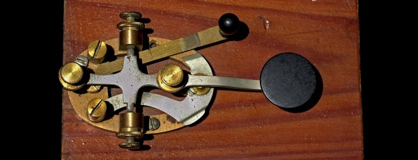
Serial communication was used long before computers existed. A predecessor is the telegraph system using Morse Code, one of the first digital modes of communication. Another predecessor is the teletype, which set standards that are still used today in your Arduino or Raspberry Pi.

All you need is two wires for serial communications, which makes it simple and relatively robust. One wire is ground and the other the signal. By interrupting the power with predefined patterns, information can be transferred over both short and long distances. The challenge is receiving the patterns correctly and quickly enough to be useful.

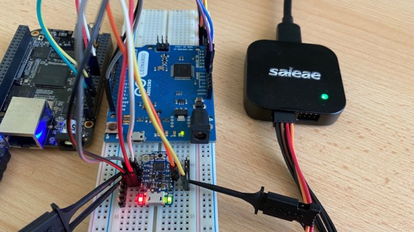
I was a bit surprised to find out the serial port on the Arduino Uno’s ATmega328P microcontroller is a Universal Synchronous Asynchronous Transmitter Receiver (USART). I’d assumed it was only a UART (same name, just leave out synchronous) probably because my first work with serial communications was with the venerable Intel 8251 “Programmable Communication Interface”, a UART, and I didn’t expect the microcontroller to be more advanced. Silly me. Later I worked with the Zilog 8530 Serial Controller Chip, a USART, the term I’ll use for both device types.

All these devices function in the same way. You send a byte by loading it into a register and it is shifted out one bit at a time on the transmit (TX) line as pulses. The receiver accepts the pulses on a receive (RX) input and shifts them into a register, which is then read by the system. The transmitter’s job is pretty easy it just shifts out the bits at a known clock rate. The receiver’s task is more complex because it needs to know when to sample the incoming signal. How it does this is the difference between asynchronous and synchronous communications.

Continue reading “Serially, Are You Syncing Or Asyncing?”