A wall clock made from wires and electronic components

Form Follows Function In This Circuit Sculpture Clock

Electronic components are strictly functional objects: their appearance is determined by the function they’re meant to fulfil. But that doesn’t mean there’s no beauty in them. In fact, a whole discipline called circuit sculpture exists that aims to make beautiful shapes out of nothing more than electronic components and wires. Today we can show you [Maarten Tromp]’s latest work in this field: a wall-mounted clock that he’s christened the Clock Sculpture.

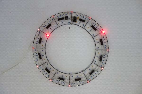
The clock’s main structure consists of two concentric rings made from galvanized steel wire, held together by twelve spokes. All components are soldered directly onto those two rings, with no additional mechanical support. Steel isn’t the greatest material for soldering to, but [Maarten] managed to make it work with a high-wattage soldering iron and a bit of plumbers’ flux.

The overall design is simple but clever: the outer ring holds 60 LEDs to indicate the minutes, with every fifth LED always illuminated dimly in order to provide a background reference in dark conditions. There are 24 LEDs on the inner ring to indicate the twelve hours as well as the “half-hours” in between. Without these, the dial would look a bit odd at 30 minutes past the hour.

Detail of a circuit sculpture clockA mains transformer, plus a single diode, a buffer capacitor and a 7805 regulator form a simple DC power supply, with its negative terminal connected to the steel frame. Time is kept by an ATtiny13A that counts mains frequency pulses. There’s no way to adjust the time: you’ll have to plug in the clock exactly at noon or midnight in order to synchronize it with the outside world. A crude method perhaps, but one that fits well with the clock’s bare-bones aesthetic.

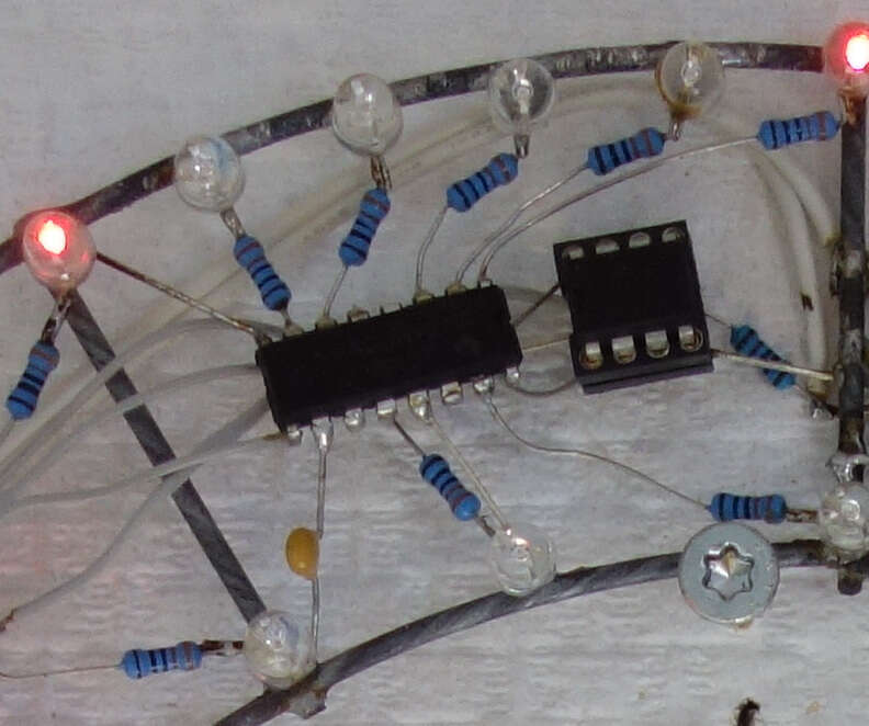
The individual LEDs are driven by a set of twelve 74HC595 shift registers, all mounted dead-bug style between the two rings. Signals and power are carried between the chips by inconspicuous grey wires taken from old IDE cables; this gives the clock a clean, uncluttered appearance. [Maarten] has had the sculpture clock in his office for several months and while it apparently took some time to get used to, he claims it’s easy to read in bright and dark conditions.

Circuit sculpture has formed the basis for several stunning clock projects: this Tie Fighter-shaped clock for instance, or this insanely complex LED clock. Our 2020 Circuit Sculpture contest yielded many breathtaking designs, too.

Large hi-res pressure sensor mat

Hi-Res, Body-Sized Pressure Sensor Mat

Hackers often find uses for pressure sensitive materials, detecting footfalls during walking or keypresses in a synthesizer being two examples. [Marco Reps] decided he’d make a hi-res, body-sized pressure sensitive mat mainly for computer-guided physiotherapy, though he wouldn’t rule out using it for gaming (twister anyone?). That meant making the equivalent of a body-sized matrix circuit of around 7000 sensors, as well as a circuit board with a multitude of shift registers. The result has a surprisingly good resolution, capable of making clearly distinguishable the heel, arch and front part of a foot.

His choice of pressure sensitive material was Velostat, a polymeric foam available as large sheets. The foam is impregnated with carbon black to make it electrically conductive, but being a foam, its resistance changes when pressure is applied. The first layer of the mat is made up of one centimeter wide strips of copper tape laid out lengthwise and spaced one centimeter apart. That’s followed by the Velostat and then another layer of copper tape oriented horizontally this time. The pressure sensors are the sandwiches formed by where the tapes overlap. In the first video below he shows how he measured and graphed the Velostat’s dynamic range to help decide to use one centimeter squares. He also puts together a smaller prototype, with good results.

Testing the mat
Testing the mat

For the body-sized mat, we count around 50 by 140 overlapping areas for a total of around 7000 one square centimeter sensors. And of course to measure each sensor in that large matrix, as you can imagine, he made up a custom circuit board with shift registers. The board works by applying positive voltage to the columns one-by-one, while each time going through all the rows and reading their voltages. Making the board was in itself was an adventure, taking a chance on a Chinese manufacturer asking only $2. But watch the second video below where he evaluates the result, including trying unsuccessfully to delaminate a board. Sadly he forgot to include places on the board for diodes, one for each column, and fixing that is another adventure he walks us through. Patience was definitely a prerequisite here, not only for making the mat, and fixing the diode problem, but also for connecting up 96-pin ribbon cables. We applaud his efforts, and his results. Check out the second video below for the making of the large mat and the circuit board.

Continue reading “Hi-Res, Body-Sized Pressure Sensor Mat”

LED display controlled by Bluetooth speaker

How Many Hacks In An LED Display?

There are so many nice hacks in [Joekutz]’s retro LED display project that it’s hard to know where to start. There’s his DIY LED display controlled by an Arduino UNO. To have some text or picture for the display, he’s wired the output of a Bluetooth speaker directly to the Arduino, and sends it speaker tones that encode the text to draw. And as if that wasn’t enough, he’s hacked a quartz driver board from an analog clock to use the display as a clock as well.

Let’s start with the LED matrix display, perhaps the best excuse for trying your hand at shift registers. This display uses two such 8-bit shift registers daisy chained together feeding two 8-bit Darlington arrays. The display has ten rows of sixteen columns, and you guessed it, the columns are controlled by the sixteen shift registers. Two Arduino pins tell the shift registers which column to turn on. The rows are turned on and off using ten transistors controlled by ten more Arduino pins. Scanning at 80 frames per second he gets a nice, flickerless display.

To make both the LED matrix circuit board and the control board, [Joekutz] carved out isolation paths in copper clad boards using his homemade CNC mill. Be sure to check out the first video below to see his misadventures with it that ultimately led to his gorgeous boards.

Continue reading “How Many Hacks In An LED Display?”

Light Duty Timekeeping: Arduino Berlin Clock

Just when we thought we’d seen all the ways there are to tell time, along comes [mr_fid]’s Berlin clock build. It’s based on an actual clock commissioned by the Senate of Berlin in the mid-1970s and erected on the famous Kurfürstendamm avenue in 1975. Twenty years later it was decommissioned and moved to stand outside the historic Europa-center.

This clock tells the time using set theory and 24-hour time. From the top down: the blinking yellow circle of light at the top indicates the passing seconds; on for even seconds and off for odd. The two rows of red blocks are the hours—each block in the top row stands for five hours, and each block below that indicates a single hour. At 11:00, there will be two top blocks and one bottom block illuminated, for instance.

The bottom two rows show the minutes using the same system. Red segments indicate 15, 30, and 45 minutes past the hour, making it unnecessary to count more than a few of the 5-minute top segments. As with the hours, the bottom row indicates one minute per light.

Got that? Here’s a quiz. What time is it? Looking at the picture above, the top row has three segments lit. Five hours times three is 15:00, or 3:00PM. The next row adds two hours, so we’re at 5:00PM. All of the five-minute segments are lit, which adds 55 minutes. So the picture was taken at 5:55PM on some even-numbered second.

The original Berlin clock suffered from the short lives of incandescent bulbs. Depending on which bulb went out, the clock could be ‘off’ by as little as one minute or as much as five hours. [mr_fid] stayed true to the original in this beautiful build and used two lights for each hour segment. This replica uses LEDs driven by an Arduino Nano and a real-time clock. Since the RTC gives hours from 0-23 and minutes and seconds from 0-59, a couple of shift registers and some modulo calculations are necessary to convert to set theory time.

[mr_fid] built the enclosure out of plywood and white oak from designs made in QCAD. The rounded corners are made from oak, and the seconds ring is built from 3/8″ plywood strips bent around a spray can. A brief tour of the clock is waiting for you after the break. Time’s a-wastin’!

Continue reading “Light Duty Timekeeping: Arduino Berlin Clock”

Shift Register Powered Realistic Candle Flicker

[Kevin Darrah] recently went out to dinner at a restaurant that was using some cheap LED candles (yuck) instead of the real thing. And in the true spirit of a hacker, he started to notice the patterns programmed into the fake flame repeat over and over again. And like any hacker might, his mind started to devise a better way.

Now’s the time where some of us lazy hackers might grab a microcontroller, and copy and paste in some pseudo-random number generating code you found on the Internet, but not [Kevin]. The basics of his hack uses two shift registers tied together that are fed a single clock signal, and also a latch signal that is slightly delayed version of the same signal made by a RC-time circuit.

The randomness of the output is created is by feeding back the outputs of the shift registers to an XOR gate. If you want to learn more about this, the technique it’s called a “linear feedback shift register“. It’s commonly used as a poor-man’s random number generator, although it’s not technically truly random, statistically it does a very good job. You can see the results in the video after the break where [Kevin] describes the circuit.  He wraps up the hack with a battery and solar charging circuit as well to make a completed project.

Continue reading “Shift Register Powered Realistic Candle Flicker”