You’ve finally decided to take the plunge and build a board with surface-mount parts. After carefully dispensing the solder paste with a syringe, it’s time to place the parts. You take up your trusty tweezers and reach to grab a SOIC-14 logic IC—only there’s not a great way to grab it. The IC is too long to grab one way and has leads obstructing the other. You work around the leads, drop the IC into place, and then pick up an 0402 resistor. You gently set the resistor into your perfectly dispensed solder paste, pull the tweezers away, and the resistor has stuck to your slightly magnetic tweezers. [Robin Reiter] realized that hobbyists and small manufacturers needed a better way to assemble their surface-mount designs, so he’s building the Pixel Pump Pick & Place, an open-source vacuum assembly tool.
Vacuum assembly tools use a blunt-tipped needle and suction to pick up surface-mount parts. Pressing an attached foot pedal disables the vacuum, allowing the part to be gently released. [Robin] thought to include a few thoughtful features to make the Pixel Pump even more useful. It has adjustable suction presets and a self-cleaning feature to blow out any solder paste you accidentally suck up. Most of the non-electronic parts are 3D printed, and [Robin] intends to make the entire design open-source.
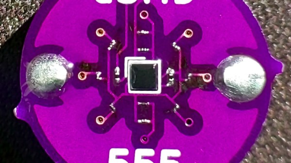
A highlight of last year’s Hackaday Remoticon was a soldering competition that had teams from around the world came together online and did the well-known MakersBox SMD Challenge kit in which a series of LED circuits of decreasing size must be soldered. The Hackaday crew acquitted themselves well, and though an 01005 resistor and LED certainly pushes a writer’s soldering skills to the limit it’s very satisfying to see it working. Lest that kit become too easy, [Arthur Benemann] has come up with something even more fiendish; his uSMD is a 555 LED flasher that uses a BGA 555 and a selection of 008004 small components.
The trick with an 01005 is to heat not the tinned and fluxed solder joint, but the trace leading up to it. If components of that size can be mastered then perhaps an 008004 isn’t that much smaller so maybe the same technique might work for them too. In his tip email to us he wrote “Soldering 008004 isn’t much worse than a 0201, you just need magnification“, and while we think he might be trolling us slightly we can see there’s no reason why it shouldn’t be do-able. Sadly he doesn’t seem to have made it available for us to buy and try so if you want to prove yourself with a soldering iron you’ll have to source the PCBs and parts yourself. Still, we suspect that if you are the type of person who can solder an 008004 then that will hardly be an onerous task for you.
We’re always fans of interesting clock builds around here, whether it’s a word clock, marble clock, or in this case a clock using a unique display method. Of course, since this is a build by Hackaday’s own [Moritz v. Sivers] the display that was chosen for this build was a custom thermochromic display. These displays use heat-sensitive material to change color, and his latest build leverages that into one of the more colorful clock builds we’ve seen.
The clock’s display is built around a piece of thermochromic film encased in clear acrylic. The way the film operates is based on an LCD display, but using heat to display the segments. For this build, as opposed to his previous builds using larger displays, he needed to refine the method he used for generating the heat required for the color change. For that he swapped out the Peltier devices for surface mount resistors and completely redesigned the drivers and the PCBs around this new method.
Of course, the actual clock mechanism is worth a mention as well. The device uses an ESP8266 board to handle the operation of the clock, and it is able to use its wireless capabilities to get the current time via NTP. All of the files needed to recreate this are available on the project page as well, including code, CAD files, and PCB layouts. It’s always good to have an interesting clock around your home, but if you’re not a fan of electronic clocks like this we can recommend any number of mechanical clocks as well.
Can I just say that doing a links roundup article in a week that includes April Fool’s Day isn’t a fun job? Because it’s not. I mean, how can you take something like reports of X-rays flowing from Uranus seriously when they release the report on such a day? It sure looks like a legitimate story, though, and a pretty interesting one. Planets emitting X-rays isn’t really a new thing; we’ve known that Jupiter and Saturn are both powerful X-ray sources for decades. Even though Uranus is the odd child of our solar system, finding evidence for X-ray emissions buried in data captured by the Chandra observatory in 2007 was unexpected. Astronomers think the X-rays might be coming from Uranus’ rings, or they might be reflections of X-rays streaming out from the sun. Or, it might be the weird alignment of the gas giant’s magnetic field causing powerful aurorae that glow in the X-ray part of the spectrum. Whatever it is, it’s weird and beautiful, which all things considered isn’t a bad way for things to be.
Another potential jest-based story popped up this week about the seemingly impossible “EmDrive”. It seems that when you appear to be breaking the laws of physics, you’re probably doing it wrong, and careful lab tests showed that fuel-free propulsion isn’t here yet. One would think it was self-obvious that filling a closed asymmetrical chamber with microwaves would produce absolutely no thrust, but EmDrive proponents have reported small but measurable amounts of thrust from the improbable engine for years. A team at TU Dresden found otherwise, though. Even though they were able to measure a displacement of the engine, it appears to be from the test stand heating up and warping as the RF energy flowed into the drive chamber. By changing the way the engine was supported, they were able to cancel out the dimensional changes that were making it look like the EmDrive was actually working.
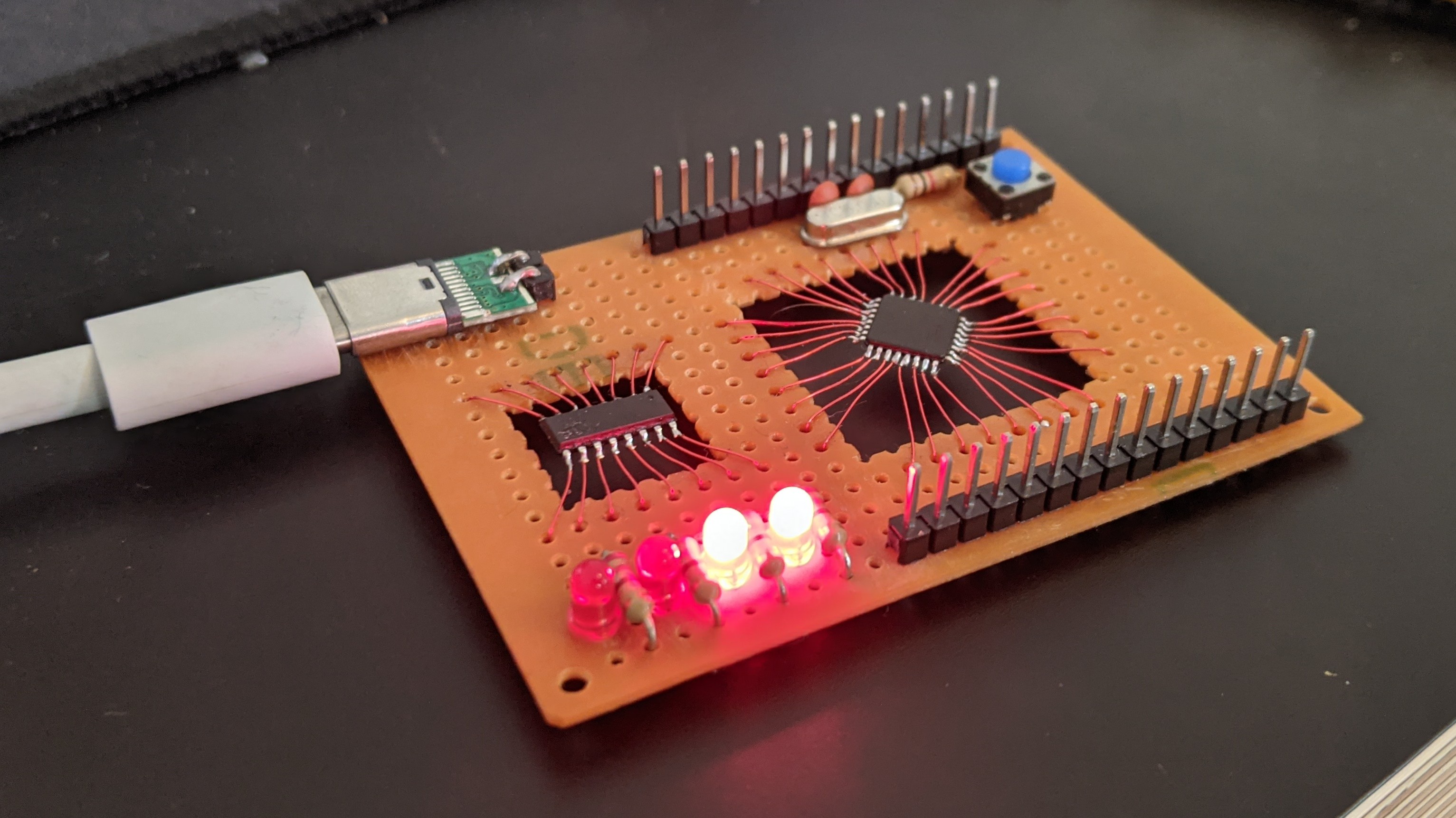
Want to use surface-mount parts, but don’t want to bother spinning up an SMD board? Not a problem, at least if you follow the lead of David Buchanan and perform no-surface surface-mount prototyping. We stumbled upon this on Twitter and thought it looked cool — it’s got a little bit of a circuit sculpture feeling, and we like the old-school look of plain 0.1″ perfboard. David reports that the flying leads are just enameled magnet wire; having done our share of scraping and cleaning magnet wire prior to soldering, we figured that part of the build must have been painful. We pinged David and asked if he had any shortcuts for prepping magnet wire, but alas, he says he just used a hot blob of solder and a little patience while the enamel cooked off. We still really like the style of this build, and we applaud the effort.
Speaking of stumbling across things, that’s one of the great joys of this job — falling down algorithmically generated rabbit holes as we troll about for the freshest hacks. One such serendipitous was this YouTube channel documenting a really nice jet engine build. We’ve seen plenty of jet engines before, but very few with afterburners like this one has. There’s also something deeply satisfying about the variable-throat nozzle that Praendy built for the engine — it’s a level of complexity that you don’t often see in hobbyist jet engines, and yet the mechanism is very simple and understandable.
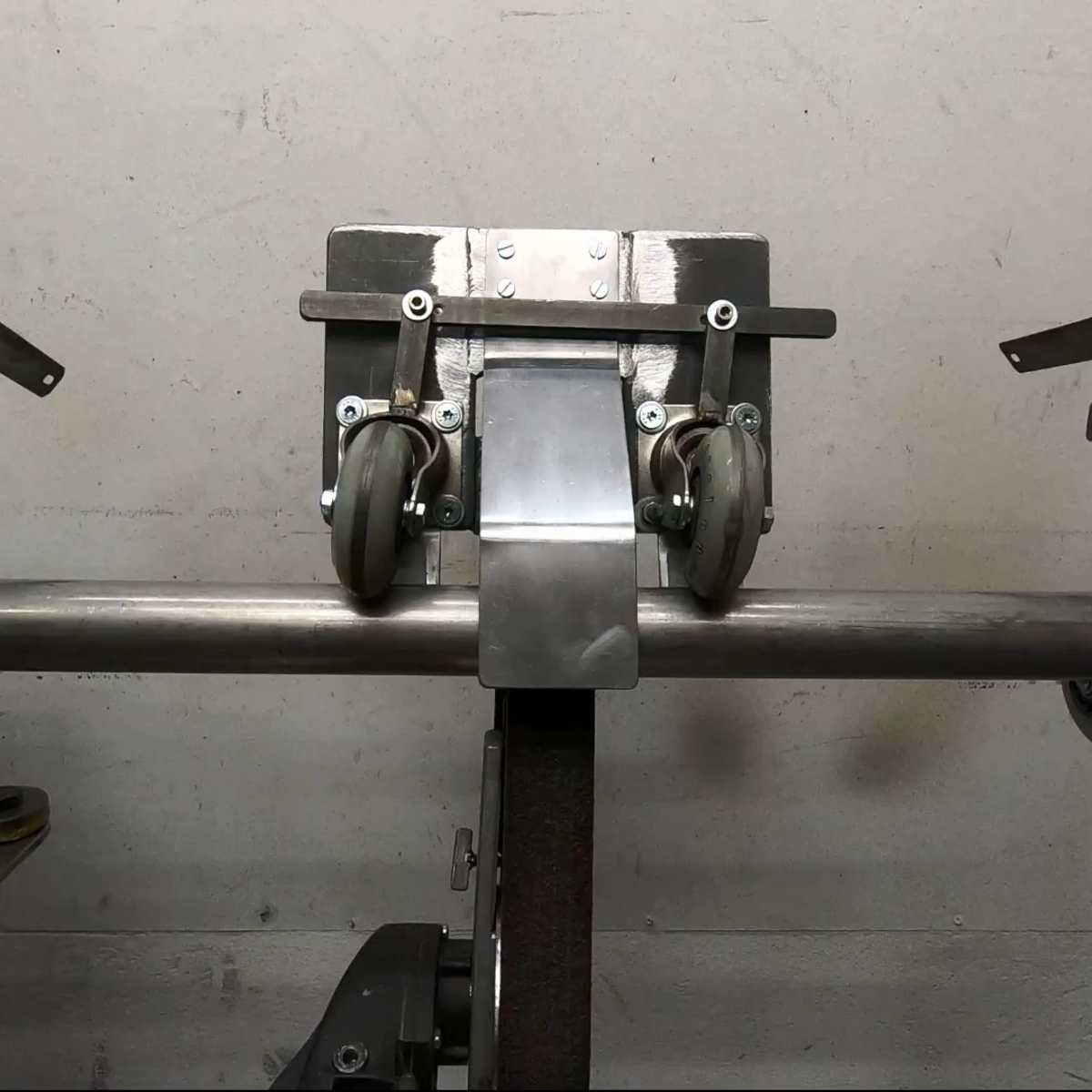
The other rabbit hole we discovered was after reporting on this cool TIG tungsten grinding tool. That took us into The Metalist’s back catalog, where we found a lot of interesting stuff. But the real treat was this automatic tube polisher (video), which we have to say kept us guessing up to the very end. If you’ve got 12 minutes and you enjoy metalworking builds at all, watch it and see if you’re not surprised by the cleverness of this tool.
And finally, we had heard of the travails of Anatoli Bugorski before, but never in the detail presented in this disturbing video. (Embedded below.)
Who is Anatoli Bugorski, you ask? He is a Russian particle physicist who, while working in an accelerator lab in 1978, managed to get his head directly in the path of a 76 GeV proton beam. Despite getting a huge dose of radiation, Bugorski not only survived the accident but managed to finish his Ph.D. and went on to a long career in nuclear physics. He also got married and had a son. He was certainly injured — facial paralysis and partial deafness, mainly — but did not suffer anything like the gruesome fates of the Chernobyl firefighters or others receiving massive radiation doses. The video goes into some detail about how the accident happened — two light bulbs are better than one, it turns out. We enjoyed the video, but couldn’t stop thinking that Bugorski was the Russian atomic-age equivalent of Phineas Gage.
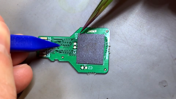
If you want to build cool things these days, you’ve probably had to master surface mount electronics. However, for many people, ball grid array (BGA) is still intimidating. Have a look at [VoltLog’s] video about his techniques for soldering BGA and inspecting that you managed to do it right.
He’s got quite a few tips about things like surface finish and flux selection. It looks easy when he does it. Of course, having a good PCB with good registration markings will help too.
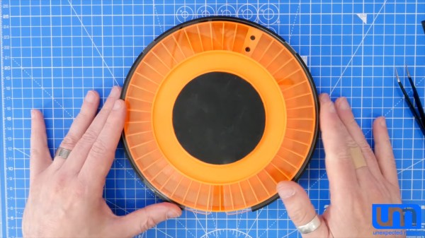
Surface mount devices were once upon a time considered a huge imposition for the electronics hobbyist. Tiny, difficult to solder by hand, and barely even labelled, many wondered whether the pastime was about to hit a brick wall entirely. Instead, enterprising hackers and makers set about learning new tricks and techniques to work with the technology, and we’ve never looked back since. [Seon] is one such enthusiast, and has built a useful turntable for making manually picking and placing boards easier. (Video, embedded below.)
The design is something [Seon] has refined gradually over time, having built two initial versions of the turntable before finally feeling ready to do a wider public release with version 3. It consists of a rotating caddy that has radial slots that hold all the tiny SMD parts, that can be labelled for easy parts identification. There’s also an acrylic window that ensures only one segment of the caddy is open at a time, to avoid accidentally dropping similar, tiny looking parts into adjacent slots – a big improvement over the first design. There’s then a smaller rotating central pad upon which a PCB can be placed, ready to receive parts.
You can do your own Surface Mount Technology based PCB assembly with just a handful of tools and some patience. At the heart of my SMT process is stopping to inspect the various steps all while trying to maintain a bit of cleanliness in the process.
Surface mount or Surface Mount Technology (SMT) is the modern way to assemble Printed Circuit Boards (PCB) and is what is commonly seen when opening a modern piece of tech. It’s much smaller than the older Through-Hole (TH) technology where the component leads were inserted into holes in PCB, and act we called “stuffing” since we had to stuff the components into the holes.
A few specialized tools make this a lot easier, but resourceful hackers will be able to pull together a solder paste stencil jig, vacuum tweezers, and a modified toaster oven with a controller that can follow the reflow profile of the solder paste. Where you shouldn’t skimp is on the quality, age, and storage of the solder paste itself.
Join me after the break for my video overview of the process I use in my workshop, along with details of every step of my SMT assembly process.