Chip Shortage Engineering: Misusing DIP Packages

After years of seeing people showing off and trading their badge Simple Add-Ons (SAOs) at Supercon, this year I finally decided to make one myself. Now for a first attempt, it would have been enough to come up with some cool PCB art and stick a few LEDs on it. But naturally I started with a concept that was far more ambitious than necessary, and before long, had convinced myself that the only way to do the thing justice was to have an onboard microcontroller.

My first thought was to go with the venerable ATtiny85, and since I already had a considerable stock of the classic eight-pin DIP MCUs on hand, that’s what I started prototyping with. After I had something working on the breadboard, the plan was to switch over to the SOIC-8 version of the chip which would be far more appropriate for something as small as an SAO.

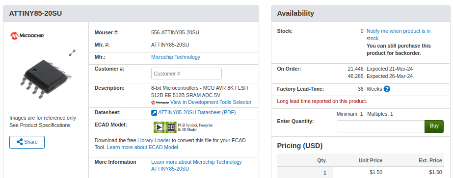
Unfortunately, that’s where things got tricky. I quickly found that none of the major players actually had the SMD version of the chip in stock. Both DigiKey and Mouser said they didn’t expect to get more in until early 2024, and while Arrow briefly showed around 3,000 on hand, they were all gone by the time I checked back. But that was only half the problem — even if they had them, $1.50 a piece seems a hell of a lot of money for an 8-bit MCU with 8K of flash in 2023.

The whole thing was made all the more frustrating by the pile of DIP8 ATtiny85s sitting on the bench, mocking me. Under normal circumstances, using them in an SAO wouldn’t really be a problem, but eight hand-soldered leads popping through the front artwork would screw up the look I had in mind.

While brooding over the situation my eyes happened to fall on one of the chips I had been fiddling with, it’s legs badly bent from repeated trips through the programmer. Suddenly it occurred to me that maybe there was a way to use the parts I already had…

Continue reading “Chip Shortage Engineering: Misusing DIP Packages”

Fail Of The Week: Z-Tape Is No Substitute For Solder

Here at Hackaday, we see all kinds of mechanical construction methods. Some are impressively solid and permanent, while others are obviously temporary in nature. The latter group is dominated by adhesives – sticky stuff like cyanoacrylate glue, Kapton tape, and the ever-popular hot glue. They’ve all got their uses in assembling enclosures or fixing components together mechanically, but surely they have no place in making solid electrical connections, right?

Maybe, maybe not. As [Tom Verbeure] relates, so-called Z-tape just might be an adhesive that can stand in for solder under certain circumstances. Trouble is, he couldn’t find the right conditions to make the tape work. Z-tape, more properly called “Electrically Conductive Adhesive Transfer Tape 9703”,  derives its nickname from the fact that it’s electrically conductive, but only in the Z-axis. [Tom] learned about Z-tape in [Joe FitzPatrick]’s malicious hardware prototyping workshop at the 2019 Hackaday Superconference, and decided to put it to the test.

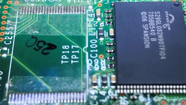
A card from a Cisco router served as a testbed thanks to an unpopulated chip footprint. The 0.5-mm pin spacing on the TSOP-48 chip was within spec for the Z-tape, but the area of each pin was 30 times smaller than the recommended minimum bonding area. While the chip was held down mechanically by the Z-tape, only five of the 48 pins were electrically connected to the pads. Emboldened by the partial success, [Tom] tried a 28-pin SOIC chip next. The larger pins and pads were still six times smaller than the minimum, and while more of the pins ended up connected by the tape, he was unable to make all 28 connections.

Reading the datasheet for the adhesive revealed that constant pressure from a clamp or clip might be necessary for reliable connections, which suggests that gluing down SMD chips is probably not the best application for the stuff. Still, we appreciate the effort, and the fine photomicrographs [Tom] made showing the particles within the Z-tape that make it work – at least in some applications.

Using Surface Mount Devices On A Breadboard

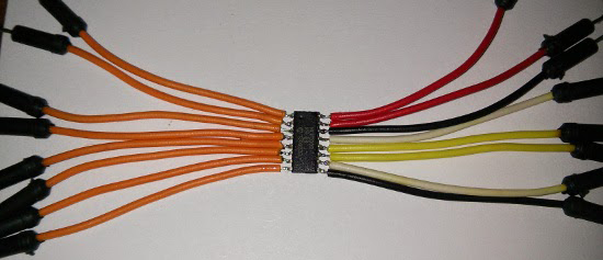
[Czar] was working on a project with the Raspberry Pi using the MCP3008 analog to digital converter. The surface mount SOIC version of this chip was slightly cheaper, and there’s always a way to make that work (Portuguese, Google Translation). How [Czar] did it is fairly impressive, as it’s a bit more flexible for breadboard designs than a through-hole version, and done correctly, is an extremely sturdy hack.

A few new leads needed to be soldered onto the SOIC package, and for this [Czar] chose jumper wires. This makes each pin easy to plug into a solderless breadboard, and since [Czar] was extremely clever, all the wires for power, ground, analog, and SPI are color coded.

Simply soldering a few jumper wires onto a chip won’t last for very long. To solve this problem, [Czar] potted the entire chip and its connections with hot glue. Probably not the best solution, and a heavy-duty epoxy would have been better, but the current build is more than enough to stand up to the relatively minor abuse it will receive on the workbench.

Surface Mount Breakout Boards

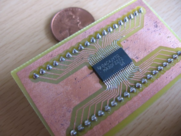
We got a hold of some DS3232 RTC chips in a 20-pin SOIC package. We’d like to have one that is breadboard compatible for easy prototyping but when we searched for SOIC20W breakout board artwork we found none. We used Eagle to design our own and you can see the finished product above which we made using the toner transfer method and cupric chloride.

You’ll find the artwork after the break in case you need to make your own breakout board some day. If you know of surface mount breakout board artwork that is freely available please leave the link in the comments for future use, or send it to us on our tips line and we’ll add it to the post.

Incidentally, the DS3232 is the same as the DS3231 used in the ChronoDot but with the addition of some SRAM. We’ll let you know if we come up with an interesting project for it.

Update: We added 28 SSOP to DIP artwork submitted by [Paul Dekker]

Continue reading “Surface Mount Breakout Boards”