High-Voltage Fun With An Inexpensive Power Supply

It used to be that nearly every home had at least one decent high-voltage power supply. Of course, it was dedicated to accelerating electrons and slamming them into phosphors so we could bathe ourselves in X-rays (not really) while watching Howdy Doody. These days the trusty tube has been replaced with LEDs and liquid crystals, which is a shame because there’s so much fun to be had with tens of thousands of volts at your disposal.

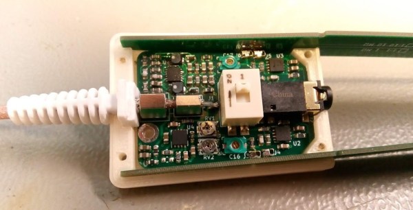
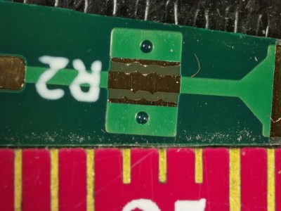
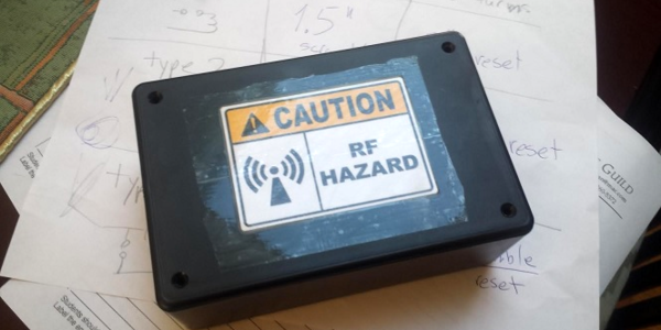
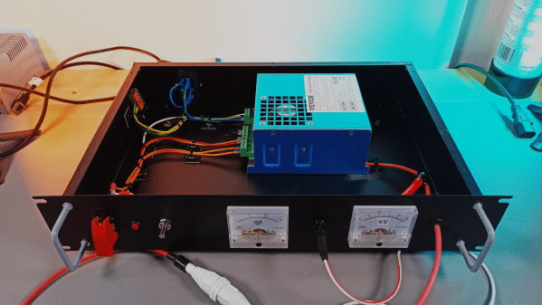
That’s the impetus behind this inexpensive high-voltage power supply by [Sebastian] over at Baltic Labs. The heavy lifting for this build is done by a commercially available power supply for a 50-watt CO2 laser tube, manufactured — or at least branded — by VEVOR, a company that seems intent on becoming the “Harbor Freight of everything.” It’s a bold choice given the brand’s somewhat questionable reputation for quality, but the build quality on the supply seems decent, at least from the outside. [Sebastian] mounted the supply inside a rack-mount case, as one does, and provided some basic controls, including the obligatory scary-looking toggle switch with safety cover. A pair of ammeters show current and voltage, the latter with the help of a high-voltage resistor rated at 1 gigaohm (!). The high-voltage feedthrough on the front panel is a little dodgy — a simple rubber grommet — but along with the insulation on the high-voltage output lead, it seems to be enough.

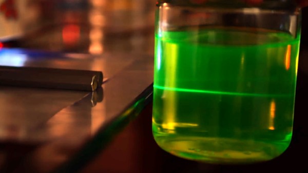
The power supply’s 30 kV output is plenty for [Sebastian]’s current needs, which from the video below appear to mainly include spark gap experiments. He does mention that 50 kV commercial supplies are available too, but it would be tough to do that for the $150 or so he spent on this one. There are other ways to go, of course — [Niklas] over at Advanced Tinkering recently shared his design for a more scratch-built high-voltage supply that’s pretty cool too. Whatever you do, though, be careful; we’ve been bitten by a 50 kV flyback supply before and it’s no joke.

Continue reading “High-Voltage Fun With An Inexpensive Power Supply”

Modern Spark Gap Transmitter Uses A Rotary Gap

In the “don’t try this at home” category, [Joe Smith] builds a spark gap transmitter with a twist. The twist is that the drive power is from a signal generator attached to a FET. From there, though, things go classic using an automotive ignition coil and a tank circuit. He shows how adjusting the spark frequency changes the signal’s sound in a standard receiver.

We say don’t try this at home because the output of a transmitter like this will likely spew RF all over the place. Granted, there’s probably not much power, but it may well irritate your neighbors.

Switching to AM, you can really hear the tone from the spark frequency in the receiver. [Joe] posted some earlier videos where he made a 160-meter spark gap transmitter using an electric fly swatter. There are more details about how the tank circuits work in those videos. You can also see what the output looks like on a spectrum analyzer. You can hear what that transmitter sounds like, too.

Continue reading “Modern Spark Gap Transmitter Uses A Rotary Gap”

Scrambling Pocket Calculators Made Easy With EMP Box V2

[Rostislav Persion] has for some time been interested in making small, portable EMP devices capable of interfering with nearby electronics. In these EMP devices, high voltage is used to create a portable spark gap generator, whose operation in turn creates electromagnetic pulses capable of resetting or scrambling nearby electronics such as pocket calculators.

Bridging adjacent holes narrows the spark gap, resulting in more frequent pulses.

His original EMP box designs relied on spark gaps constructed from metal screws threaded into a clear plastic insulator, but this newest design ditches fussy screw adjustments and relies on perfboard. By cutting out a single row of plated perfboard holes and soldering the high voltage terminals to each end, the empty holes in between form the essential parts of a spark gap.

It’s even adjustable: one simply bridges adjacent holes with solder to effectively decrease the gap. As for generating the high voltage itself, a DC voltage multiplier from Amazon takes care of that. Watch the device reset some calculators in the short video below.

Looking for high-voltage experiments that aren’t so sketchy? Get yourself a Van de Graff generator, some metal balls, and a little bit of oil, and make some art.

Continue reading “Scrambling Pocket Calculators Made Easy With EMP Box V2”

triggered spark gap

Spark Plug And Plumbing Parts Bring Nitrogen Laser Under Control

When it comes to high-speed, high-voltage switching, there are a wealth of components to choose from — MOSFETS, thyristors, IGBTs, and even vacuum tubes like thyratrons. But who needs all that expensive silicon (or glass) when all you need to build a high-voltage switch is some plumbing fixtures and a lathe?

At least that’s the approach that budget-minded laser experimenter [Les Wright] took with his latest triggered spark gap build. We’ve been watching his work for a while now, especially his transversely excited atmospheric (TEA) lasers. These are conceptually simple lasers that seem easy to build, at least compared to other lasers. But they do require a rapid pulse of high voltage across their long parallel electrodes to lase, and controlling the pulse is where this triggered spark gap shines.

The spark gap is made from brass plumbing fittings on either end of a short PVC coupler. [Les] used his lathe to put a thread into one of the caps to accept a spark plug, the center electrode of which pokes through a small hole in the metal cathode. To trigger the spark gap, [Les] built a trigger generator that outputs about 15,000 volts, which arcs from the spark plug electrode to the spark gap cathode in the low-pressure nitrogen environment. Little spark leads to big spark, big spark discharges a capacitor across the laser electrodes, and you’ve got a controlled single-shot laser. Check it out in the video below.

Honestly, the more we see of [Les]’ videos, the more we want to play with lasers and high voltage. From DIY doorknob caps to blasting Bayer arrays off cheap CCD cameras, there’s always something fun — and slightly dangerous — going on in [Les]’s lab.

Continue reading “Spark Plug And Plumbing Parts Bring Nitrogen Laser Under Control”

This Modular Differential Probe Shows Great Attention To Detail

[Petteri Aimonen] presents for us a modular differential probe, as his entry into the 2021 Hackaday Prize.

This project shows a simple and well polished implementation of a differential-to-single-ended preamplifier, which allows a differential signal to be probed and fed to an oscilloscope via a BNC cable.

PCB Spark gap for primary ESD protection

It implements a classic instrumentation amplifier, where we have two amplifier stages. The first gives us the options for a gain of either 1 or 10, if we need it, with the second stage having a gain of 2.

The remaining circuit is a power supply to generate the necessary dual-rail supplies to feed the opamps. There is a lot of filtering on those output rails as well as on the USB power input side to try keep all that switched-mode power supply noise out of the signal path.

There are a couple of interesting design choices including the use of PCB material for the long removable probe arms, that integrate PCB spark gaps to offer a first defence against ESD reaching the more delicate parts of the system.

Why This Is Useful

There are two main classes of signals we electronics engineers care about: single-ended and differential-mode.

With the first kind, the signal is carried on a single wire, which is defined as being referenced to the common system ground. Current flows along the wire and returns to its source along the path of least resistance, at least at low frequencies. At higher frequencies, the path of least inductance is more relevant. This is all well and good, so long as you design the PCB correctly.

Coupling from adjacent wires due to mutual capacitance and inductance, as well as noise in the reference ground all conspire to mangle the signal we want to pass down the wire.

As the frequencies increase, and especially if you’re dealing with sharp edges, with all that extra odd-harmonic power, things start to get bad real fast. The way we deal with this is by utilising differential-mode signalling. This is where instead of a single wire, referenced to some notion of ground, we send the signal down a pair of wires, where the voltage difference between the wires forms the signal. Any external noise that leaks into the pair, will (hopefully!) affect both wires equally, forming what we call a common-mode component. When you look at the difference, this common mode noise disappears. (Our own [Bil Herd] covered this some time ago.)

When probing a circuit, it pays to have the right kind of probe as well as an understanding of the effect the probe will have on the circuit in operation. If you have a single-ended signal and you want to view it on your scope, your choice is either a passive or active probe. Usually some kind of passive probe will be most available. These commonly come in 50 Ω and 1 MΩ versions, and you need to be careful to use the correct probe type for your application.

For probing differential signals, it is possible to use a pair of probes, one for each signal wire, and then utilise the scope’s math difference function to show the signal. This is quite often a desperate measure, and what you really want is a differential front-end in hardware. You need a differential active probe.

The circuit may be simple, but don’t underestimate how much tweaking it needs to have good performance – a little slip with the PCB layout, as the author describes, caused some annoying resonances which can be hard to track down.

The project is still under active development, with the author showing the process as the project progresses, but its looking pretty good already, if you ask us.

Sources can found on his GitHib, which uses all Open Source tools, so its pretty accessible too.

Is That An EMP Generator In Your Pocket Or Is My Calculator Just Broken?

Ah, what fond memories we have of our misspent youth, walking around with a 9,000-volt electromagnetic pulse generator in our Levi’s 501s and zapping all the electronic devices nobody yet carried with them everywhere they went. Crazy days indeed.

We’re sure that’s not at all what [Rostislav Persion] had in mind when designing his portable EMP generator; given the different topologies and the careful measurement of results, we suspect his interest is strictly academic. There are three different designs presented, all centering around a battery-powered high-voltage power module, the Amazon listing of which optimistically lists as capable of a 400,000- to 700,000-volt output. Sadly, [Rostislav]’s unit was capable of a mere 9,000 volts, which luckily was enough to get some results.

Coupled to a spark gap, one of seven different coils — from one to 40 turns — and plus or minus some high-voltage capacitors in series or parallel, he tested each configuration’s ability to interfere with a simple pocket calculator. The best range for a reset and scramble of the calculator was only about 3″ (7.6 cm), although an LED hooked to a second coil could detect the EMP up to 16″ (41 cm) away. [Rostislav]’s finished EMP generators were housed in a number of different enclosures, one of which totally doesn’t resemble a pipe bomb and whose “RF Hazard” labels are sure not to arouse suspicions when brandished in public.

We suppose these experiments lay to rest the Hollywood hype about EMP generators, but then again, their range is pretty limited. You might want to rethink your bank heist plans if they center around one of these designs.

Continue reading “Is That An EMP Generator In Your Pocket Or Is My Calculator Just Broken?”

The Devil Is In The Details For This Open Air Laser

Normally, we think of lasers as pretty complex and fairly intimidating devices: big glass tubes filled with gas, carefully aligned mirrors, cooling water to keep the whole thing from melting itself, that sort of thing. Let’s not even get started on the black magic happening inside of a solid state laser. But as [Jay Bowles] shows in his latest Plasma Channel video, building a laser from scratch isn’t actually as difficult as you might think. Though it’s certainly not easy, either.

The transversely excited atmospheric (TEA) laser in question uses high voltage passed across a a pair of parallel electrodes to excite the nitrogen in the air at standard atmospheric pressure, so there’s no need for a tube and you don’t have to pull a vacuum. The setup shakes so many UV photons out of the nitrogen that it doesn’t even need any mirrors. In fact, you should be able to get almost all the parts for a TEA laser from the hardware store. For example, the hexagonal electrodes [Jay] ends up using are actually 8 mm hex keys with the ends cut off.

Continue reading “The Devil Is In The Details For This Open Air Laser”