Motorized Camera Slider Rides On Carbon

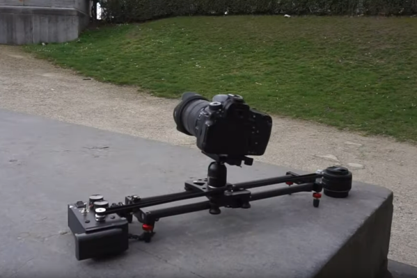
While not every camera mount needs to have six degrees of freedom, one or two can be extremely helpful in the photographic world. In order to make time-lapse shots with some motion or shots that incorporate some parallax, a moving camera mount or dolly is needed, and this small one builds upon a pre-existing, although non-motorized, camera slider.

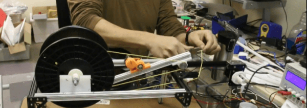
The slider is an inexpensive model from everyone’s favorite online warehouse, with rails that are at least coated in carbon, if not made out of it entirely, to ensure smooth camera motion. To add the motorization to automatically move the camera, a stepper motor with a belt drive is used which is controlled by an Arduino. A few limit switches are added, letting the dolly perform different movement patterns automatically, and a pair of potentiometers for fine and coarse speed control are included as well, letting the camera take both time-lapse and video while using this mount at various controllable speeds.

With everything tucked into a relatively small box at one end of the dolly, the build is both accessible and functional. The code for the microcontroller is also available on the project’s GitHub page for anyone looking to replicate or build upon the project. And, for those looking to add more degrees of freedom to their camera setups, take a look at this DIY pan and tilt mount.

Continue reading “Motorized Camera Slider Rides On Carbon”

How Current Shunts Work

Current. Too little of it, and you can’t get where you’re going, too much and your hardware’s on fire. In many projects, it’s desirable to know just how much current is being drawn, and even more desirable to limit it to avoid catastrophic destruction. The humble current shunt is an excellent way to do just that.

Ohm’s Law.

To understand current, it’s important to understand Ohm’s Law, which defines the relationship between current, voltage, and resistance. If we know two out of the three, we can calculate the unknown. This is the underlying principle behind the current shunt. A current flows through a resistor, and the voltage drop across the resistor is measured. If the resistance also is known, the current can be calculated with the equation I=V/R.

This simple fact can be used to great effect. As an example, consider a microcontroller used to control a DC motor with a transistor controlled by a PWM output. A known resistance is placed inline with the motor and, the voltage drop across it measured with the onboard analog-to-digital converter. With a few lines of code, it’s simple for the microcontroller to calculate the current flowing to the motor. Armed with this knowledge, code can be crafted to limit the motor current draw for such purposes as avoiding overheating the motor, or to protect the drive transistors from failure.

In fact, such strategies can be used in a wide variety of applications. In microcontroller projects you can measure as many currents as you have spare ADC channels and time. Whether you’re driving high power LEDs or trying to build protection into a power supply, current shunts are key to doing this.

Continue reading “How Current Shunts Work”

Possibly The Most Up-Cycled, Hacked E-Bike You’ll See All Week

When it comes to bringing an idea to life it’s best to have both a sense of purpose, and an eagerness to apply whatever is on hand in order to get results. YouTube’s favorite Ukrainians [KREOSAN] are chock full of both in their journey to create this incredible DIY e-bike using an angle grinder with a friction interface to the rear wheel, and a horrifying battery pack made of cells salvaged from what the subtitles describe as “defective smartphone charging cases”.

Battery pack made from cells salvaged out of defective equipment. Sometimes, you use what you have on hand.

What’s great to see is the methodical approach taken to creating the bike. [KREOSAN] began with an experiment consisting of putting a shaft on the angle grinder and seeing whether a friction interface between that shaft and the tire could be used to move the rear wheel effectively. After tweaking the size of the shaft, a metal clamp was fashioned to attach the grinder to the bike. The first test run simply involved a long extension cord. From there, they go on to solve small problems encountered along the way and end up with a simple clutch system and speed control.

The end result appears to work very well, but the best part is the pure joy (and sometimes concern) evident in the face of the test driver as he reaches high speeds on a homemade bike with a camera taped to his chest. Video is embedded below.

Continue reading “Possibly The Most Up-Cycled, Hacked E-Bike You’ll See All Week”

DIY Wire Spooler With Clever Auto-Tensioning System

[Solarbotics] have shared a video of their DIY wire spooler that uses OpenBeam hardware plus some 3D printed parts to flawlessly spool wire regardless of spool size mismatches. Getting wire from one spool to another can be trickier than it sounds, especially when one spool is physically larger than the other. This is because consistently moving wire between different sizes of spools requires that they turn at different rates. On top of that, the ideal rate changes as one spool is emptying and the other gets larger. The wire must be kept taut when moving from one spool to the next; any slack is asking for winding problems. At the same time, the wire shouldn’t be so taut as to put unnecessary stress on it or the motor on the other end.

There aren’t any build details but the video embedded below gives a good overview and understanding of the whole system. In the center is a tension bar with pulleys on both ends though which the wire feeds. This bar pivots at the center and takes up slack while its position is encoded by turning a pot via a 3D printed gear. Both spools are motor driven and the speed of the source spool is controlled by the position of the tension bar. As a result, the bar automatically takes up any slack while dynamically slowing or speeding the feed rate to match whatever is needed.

Continue reading “DIY Wire Spooler With Clever Auto-Tensioning System”

Beautiful Cardboard Robot Build

[Miloslav Stibor] may have built Mimobot 2.1 out of cardboard so that it’s not very heavy, but the robot is absolutely no lightweight. Read through his logs (in Czech, or in translation) and you’ll see what we mean.

Our favorite feature is the recharging dock and docking connectors, made respectively out of spring-loaded rivet ferrules and copper-tape-covered cardboard. The video found on that page is also absolutely brilliant: watch in awe as it climbs over children’s books, pulls a wooden train, or scales a mountain of pillows.

We wrote [Miloslav] and asked about the continuous-rotation servos, because they ran so smoothly at low speeds. He replaced the potentiometer with a pair of “carefully matched” 2.2 k resistors, and drives them with a PWM signal. Sounds easy, and obviously works very well. We were always under the impression that it was a little bit more complicated to get proportional control of hobby servos. We’ll have to experiment.

The wheels and lightweight frame (made of “military grade” cardboard — saturated with a wood/paper glue) make it entirely capable in living-room environments covered in cables or rugs, which is something we can’t say about our purchased vacuum-cleaner-bot. And the cell-phone remote interface that lets him control the onboard camera and its elevation and lighting. Driving the thing around with the phone control looks fun.

In short, if you build small robots, give this one a look. Something very much like this is now on our short must-build list. And we can’t wait to see Mimobot v3!