Better 3D Scans Through A Slowed Down Turntable

3D scanners aren’t cheap, and the last thing you want to see after purchasing one is bad data. But that’s what [Dave Does] and others were getting from their Revopoint POP scanners until some communal brainstorming uncovered the reason: the motorized turntable that came with the Kickstarter edition of the product was spinning too fast for the software to accurately keep track of the object. So he decided to replace the stepper motor controller in his turntable and document the process for anyone else who’s scanner might be struggling.

Plenty of room for expansion.

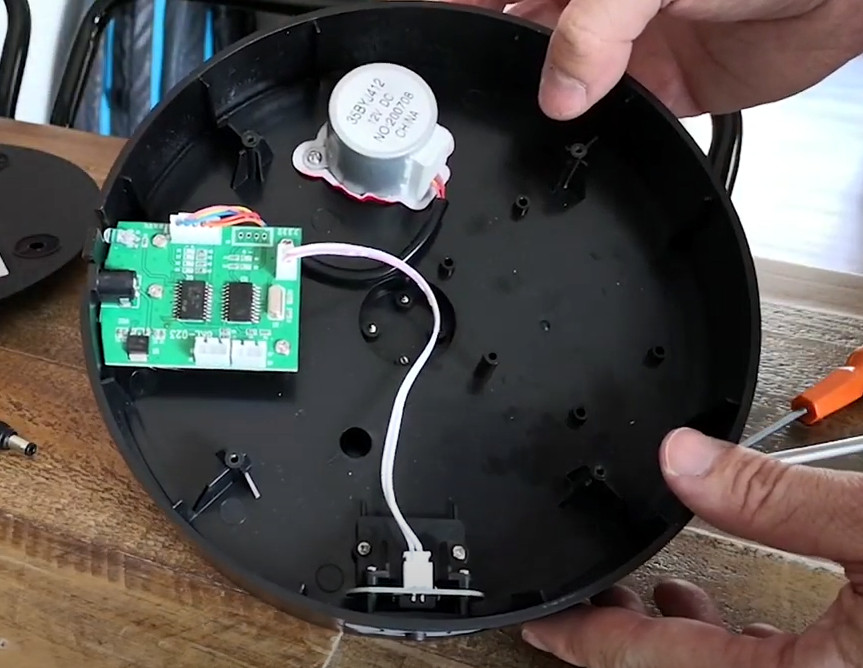
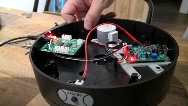
In the video below, [Dave] pops open the plastic case of the turntable and reveals a pretty sparse interior. There’s an incredible amount of empty space inside, and even some mounting studs to screw down new components, should you want to get into some hardcore upgrades. But for his purposes, a generic stepper motor controller that featured a potentiometer to adjust the speed was enough. He found a suitable board online for around $5 USD, and got to designing a 3D printed bracket that mates up to the existing screw holes on the turntable.

But it’s not exactly a drop-in replacement. For one thing, you’ve got to pop a hole in the side of the enclosure for the potentiometer knob to stick out of. You’ve also got to solder wires coming from the original DC jack and power switch to the new board to get it hooked up, but at least the motor plugs right in. In the video below, you can see [Dave] demonstrate the impressively deep throttle capability of the new driver.

If you’d rather build than buy, we’ve covered some impressive DIY turntables in the past that could fit the bill nicely, from automatic models that handle camera control to fully 3D printed versions that you’ve got to crank yourself.

Continue reading “Better 3D Scans Through A Slowed Down Turntable”

Stepper Motors Quick And Simple

If you want a simple and easy introduction to stepper motors, check out the [IMSAI Guy]’s short video where he designs a very basic stepper motor controller and packs in a lot of quick lessons along the way. (Embedded below.)

He first goes over the fundamentals of a stepper motor in a practical, hands-on approach, and also shows us how to ring out the connections if the pinout is unknown. Next he demonstrates stepping the motor manually and then makes a simple FET driver circuit. Just when you’re expecting a small microcontroller to appear, the [IMSAI Guy] instead digs deep into his junk box and explains how to drive the motor with a 22V10 GAL (an electrically erasable PAL) and a 555 timer module. Based on a clearly-explained logic table for driving the coils, a sneaky way to introduce Karnaugh maps, he proceeds to write the output equations in WinCUPL.

Mature Readers will recall the “Happy PAL” Character

WinCUPL is the modern version of CUPL (Compiler for Universal Programmable Logic) originally written by a company called Assisted Technology, now owned by Altium. CUPL and peers like PALASM from Monolithic Memories, Inc. (MMI) and ABEL from Data I/O Corporation were basic Hardware Description Languages specifically designed for PALs, GALs, and CPLDs. PALs were small arrays of logic gates with fusible interconnections, and your design is “burned” into the fuses much like a (EE)PROM. When designing with PALs, you could clearly visualize the connections in your mind, something that has since been remedied by the advent of modern FPGAs.

Alas, he cuts out the part where the source code is compiled and the 22V10 is programmed, and jumps directly into testing the circuit on a breadboard. Spoiler alert — it does work. Zooming in close and squinting, the nifty 555 timer breadboard module that he points out is called a TP353, which you can find from your favorite online supplier.

There is a lot to learn in this tutorial, and the [IMSAI Guy] does a great job at making the subject approachable to hobbyists and novices. We also covered another of his tutorials a couple of weeks ago on image sensors. Thanks to [itsevilbert] for the tip.

Continue reading “Stepper Motors Quick And Simple”

Pulse Generator Tells Your Motors “Get Ta Steppin”

Stepper Motor Pulse Generator

Stepper motors are great for a bunch of projects; CNC machines, clocks or robots for example. Sometimes when working on a project that does include a stepper motor and driver, it would be nice to test that part of the build without hooking everything up. A pulse generator could be used to complete such a task and [CuteMinds] has put together a DIY friendly version tailored specifically for stepper motors. This device makes quick and easy work for testing out those stepper motors.

At the heart of the pulse generator is a 12F675 microchip which looks to the resistance value of a potentiometer to adjust the square wave step signal output from 20hz to 3khz. Just having the step signal would pretty cool but this project goes a little farther. There are 3 sets of headers on the board that allow you to connect either a jumper or switch in order to: 1) turn the power on, 2) enable the stepper driver and 3) select the direction the motor turns. The on-board batteries make this unit portable for remote usage.

If you are itching to make one for yourself, the Eagle schematic and board files are available for download at the above link.

Building A Stepper Driver

[TBJ] is building what he calls a junkbox 3D printer. You can probably guess that he’s trying to salvage most of the parts for the device, and after pulling a stepper motor from an old printer he was in need of a way to control it. What he came up with is a stepper driver that uses discrete components that are easy to acquire and inexpensive. The design calls for two inputs, one that toggles the direction in which the motor will spin, and the other that triggers one step of the motor. A CD4013 dual flip-flop takes care of both of these inputs in one chip package.

The motor is driven by a pair of H-bridges that he built using six transistors each. The trick with a stepper motor is that you need to drive the four poles of the motor to a specific logic level at a specific time. For this [TBJ] uses a CD4017 decade counter. A network of diodes grounds half of the output lines based on the flip-flop that controls direction. Our friend the 555 timer provides a clock for the circuit, keeping everything moving at a predefined rate. Check out the video after the break for an explanation and demonstration.

Continue reading “Building A Stepper Driver”