This Arduino Pen Plotter Is Built For Speed

We see a lot of simple pen plotter projects around here, and while we appreciate them one and all, most of them are a little on the slow side. That’s OK — a glacial pace is sometimes all that’s needed, as long as it gets the job done. But there’s nothing wrong with putting the pedal to the metal, so to speak. And that’s exactly what this super-fast Arduino-based plotter is all about.

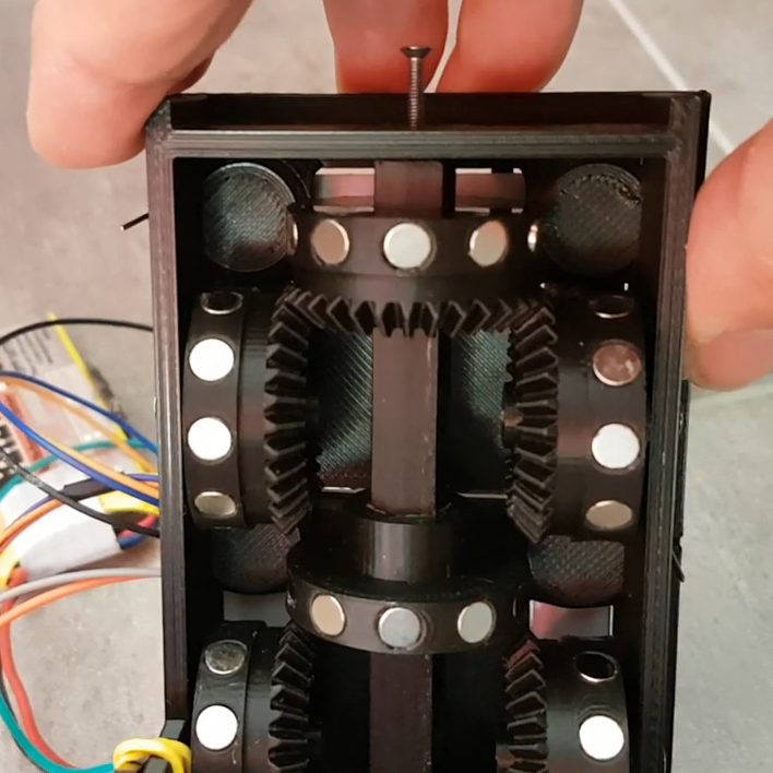
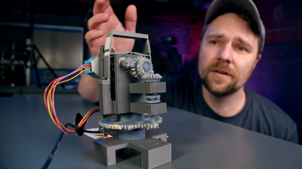
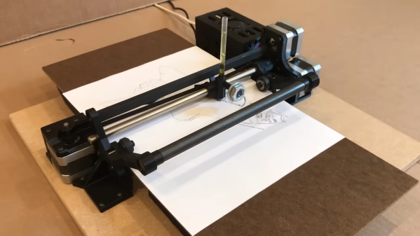
As the story goes, [IV Projects] felt the need for speed after building an earlier pen plotter project that worked, but failed to excite. With the additional goal of keeping the plotter easy to build with cheap parts, the design centers on a “grit roller drive” for the Y-axis — the one that actually moves the paper back and forth. And move it does, using Dremel tool sanding drums on a lightweight shaft to maximize acceleration. In fact, all the moving parts are kept as lightweight as possible, and the results really show — the three steppers really sing when this plotter is in action.

There are some really clever details in [IV Projects]’ design. We particularly like the way the pen lift mechanism works, and the surprise appearance of a clothespin spring as a belt tensioner was a real treat. Judging by the pile of rejected prototype parts, it took quite a bit of work to get this design right. If you’d like to build your own, STLs are available for the printed parts.

If you’re interested in what the other end of the speed scale looks like, check out this bare-minimum pen plotter.

Continue reading “This Arduino Pen Plotter Is Built For Speed”

Automate Parts Kitting With This Innovative SMD Tape Slicer

Nobody likes a tedious manual job prone to repetitive stress injury, and such tasks rightly inspire an automated solution. This automatic SMD tape cutter is a good example of automating such a chore, while leaving plenty of room for further development.

We’re used to seeing such tactical automation projects from [Mr Innovative], each of which centers on an oddly specific task. In this case, the task involves cutting a strip containing a specific number of SMD resistors from a reel, perhaps for assembling kits of parts. The mechanism is simple: a stepper motor with a rubber friction wheel to drive the tape, and a nasty-looking guillotine to cut the tape. The cutter is particularly interesting, using as it does a short length of linear bearing to carry a holder for a razor blade that’s mounted perpendicular to the SMD tape. The holder is mounted to a small motor via a crank, and when the proper number of parts have been fed out, the motor rotates one revolution, driving the angled blade quickly down and then back up. This results in a shearing cut rather than the clipping action seen in this automated wire cutter, also by [Mr Innovative].

Curiously, there seems to be no feedback mechanism to actually measure how many resistors have been dispensed. We assume [Mr Innovative] is just counting steps, but it seems easy enough to integrate a photosensor to count the number of drive sprocket holes in the tape. It also seems like a few simple changes would allow this machine to accommodate SMD tapes of different sizes, making it generally useful for SMD kitting. It’s still pretty cool as a tactical project, though, and does a great job inspiring future improvements.

Continue reading “Automate Parts Kitting With This Innovative SMD Tape Slicer”

Bring Precision To The Woodshop With An Electronic Router Lift

One of the knocks that woodworkers get from the metalworking crowd is that their chosen material is a bit… compliant. Measurements only need to be within a 1/16th of an inch or so, or about a millimeter, depending on which side of the Atlantic you’re on. And if you’re off a bit? No worries, that’s what sandpaper is for.

This electronic router lift is intended to close the precision gap and make woodworking a bit less subjective. [GavinL]’s build instructions are clearly aimed at woodworkers who haven’t dabbled in the world of Arduinos and stepper motors, and he does an admirable job of addressing the hesitancy this group might feel when tackling such a build. Luckily, a lot of the mechanical side of this project can be addressed with a commercially available router lift, which attaches to a table-mounted plunge router and allows fine adjustment of the cutting tool’s height from above the table.

What’s left is to add a NEMA 23 stepper to drive the router lift, plus an Arduino to control it. [GavinL] came up with some nice features, like a rapid jog control, a fine adjustment encoder, and the ability to send the tool all the way up or all the way down quickly. Another really nice touch is the contact sensor, which is a pair of magnetic probes that attach temporarily to the tool and a height gauge to indicate touch-off. Check the video below to see it all in action.

One quibble we have with [GavinL]’s setup is the amount of dust that the stepper will be subjected to. He might need to switch out to a dustproof stepper sooner rather than later. Even so, we think he did a great job bridging the gap between mechatronics and woodworking — something that [Matthias Wandel] has been doing great work on, too.

Continue reading “Bring Precision To The Woodshop With An Electronic Router Lift”

Raspberry Pi Test Stand Tells You Which Glues To Use

Not all glues are created equal; or rather, not every glue is good for every application. But how is one to know which glue to use in which kinds of joints? The answer to that is not always clear, but solid numbers on the comparative strength of different glues are a great place to start.

To quantify what can ordinarily be a somewhat subjective process, there’s probably no one better than woodworker and hacker [Matthias Wandel], equipped as he is with his DIY strength-tester. Using its stepper-driven power to blast apart glued lap joints, [Matthias] measured the yield point of the various adhesives using a strain gauge connected to a Raspberry Pi.

His first round of tests had some interesting results, including the usually vaunted construction adhesive ending up in a distant last place. Also performing poorly, at least relative to its reputation and the mess it can cause, was the polyurethane-based Gorilla Glue. A surprise standout in overall strength was hot glue, although that seemed to have a sort of plastic yield mode. Ever the careful empiricist, [Matthias] repeated his tests using hardwoods, with remarkably different results; it seems that glues really perform better with denser wood. He also repeated a few tests to make sure every adhesive got a fair shake. Check out the video below for the final results.

It’s always good to see experiments like this that put what we often take for granted to the test. [John] over at the Project Farm channel on YouTube does this kind of stuff too, and even did a head-to-head test of epoxy adhesives.

Continue reading “Raspberry Pi Test Stand Tells You Which Glues To Use”

One Stepper Plus A Whole Bunch Of Magnets Equals A Unique Seven-Segment Display

Sometimes the cost of simplicity is extra complexity. It seems counterintuitive, but it seems to be true. And this single-motor mechanical seven-segment display seems to be a perfect example of this paradox.

On second thought, [aeropic]’s mechanism isn’t really all that mechanically complicated, but there sure was a lot of planning and ingenuity that went into it. The front has a 3D-printed bezel with the familiar segment cutouts, each of which is fitted with a pivoting segment, black on one side and white on the other.

Behind the bezel is a vertical shaft with three wheels, one behind each horizontal segment, and a pair of horizontal shafts, each with two wheels behind each vertical segment. The three shafts are geared to turn together by a single stepper in the base. Each wheel has ten magnets embedded in the outer circumference, with the polarity oriented to flip the segment in front of it to the right orientation for the current digit. It’s probably something that’s most easily understood by watching the video below.

We’ve seen quite a few of these mechanical seven-segment displays lately — this cam-and-servo mechanism comes to mind. We love them all, of course, but the great thing about [aeropic]’s display is how quiet it is — the stepper is mostly silent, and the segments make only a gentle clunk when they flip. It’s very satisfying.

Continue reading “One Stepper Plus A Whole Bunch Of Magnets Equals A Unique Seven-Segment Display”

That Clock On The Wall Is Actually A Network Ping Display

We’ve all been online from home a bit more than usual lately, in ways that often stretch the limits of what our ISP can muster. You know the signs — audio that drops out, video sessions that make you look like [Max Headroom], and during the off-hours, getting owned in CS:GO by pretty much everyone. All the bandwidth in the world won’t make up for high latency, and knowing where you stand on that score is the point of this ping-tracking clock.

This eye-catching lag-o-meter is courtesy of [Charl], who started the build with a clock from IKEA. Stripped of pretty much everything but the bezel, he added a coaxial clock motor and a driver board, along with a custom-printed faceplate with logarithmic scale. The motors are driven by an ESP32, which uses internet control message protocol (ICMP) to ping a trusted server via WiFi, calculates the proper angles for the hands, and drives the motors to show you the bad news. There’s also an e-paper display in the face, showing current server and WiFi settings.

We really like how this clock looks, and if it wasn’t for the fact that the numbers it displays would often be too depressing to bear, we’d build one in a snap. If facing the painful truth isn’t your style, there are other neat ICMP tricks that you can try instead.

JWST mirror actuator model

Working Model Reveals Amazing Engineering Of Webb’s Mirror Actuators

We end up covering a lot of space topics here on Hackaday, not because we’re huge space nerds — spoiler alert: we are — but because when you’ve got an effectively unlimited budget and a remit to make something that cannot fail, awe-inspiring engineering is often the result. The mirror actuators on the James Webb Space Telescope are a perfect example of this extreme engineering, and to understand how they work a little better, [Zachary Tong] built a working model of these amazing machines.

The main mirror of the JWST is made of 18 separate hexagonal sections, the position of each which must be finely tuned to make a perfect reflector. Each mirror has seven actuators that move it through seven degrees of freedom — the usual six that a Stewart platform mechanism provides, plus the ability to deform the mirror’s curvature slightly. [Zach]’s model actuator is reverse-engineered from public information (PDF) made available by the mirror contractor, Ball Aerospace. While the OEM part is made from the usual space-rated alloys and materials, the model is 3D printed and powered by a cheap stepper motor.

That simplicity belies the ingenious mechanism revealed by the model. The actuators allow for both coarse and fine adjustments over a wide range of travel. A clever tumbler mechanism means that only one motor is needed for both fine and coarse adjustments, and a flexure mechanism is used to make the fine adjustments even finer — a step size of only 8 nanometers!

Hats off to [Zach] for digging into this for us, and for making all his files available in case you want to print your own. You may not be building a space observatory anytime soon, but there’s plenty about these mechanisms that can inform your designs.

Continue reading “Working Model Reveals Amazing Engineering Of Webb’s Mirror Actuators”