Speaking The Same Language As A Wireless Thermometer

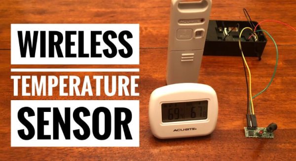
Temperature is a delicate thing. Our bodies have acclimated to a tight comfort band, so it is no wonder that we want to measure and control it accurately. Plus, heating and cooling are expensive. Measuring a single point in a dwelling may not be enough, especially if there are multiple controlled environments like a terrarium, pet enclosure, food storage, or just the garage in case the car needs to warm up. [Tim Leland] wanted to monitor commercially available sensors in several rooms of his house to track and send alerts.

The sensors of choice in this project are weather resistant and linked in his project page. Instead of connecting them to a black box, they are linked to a Raspberry Pi so your elaborate home automation schemes can commence. [Tim] learned how to speak the thermometer’s language from [Ray] who posted about it a few years ago.

The system worked well, but range from the receiver was only 10 feet. Thanks to some suggestions from his comments section, [Tim] switched the original 433MHz receiver for a superheterodyne version. Now the sensors can be a hundred feet from the hub. The upgraded receiver is also linked on his page.

We’ve delved into thermocouple reading recently, and we’ve featured [Tim Leland] and his 433MHz radios before.

Temperature Logger

Logging Engine Temperature For RC Models

[Rui] enjoys his remote-controlled helicopter hobby and he was looking for a way to better track the temperature of the helicopter’s engine. According to [Rui], engine temperature can affect the performance of the craft, as well as the longevity and durability of the engine. He ended up building his own temperature logger from scratch.

The data logger runs from a PIC 16F88 microcontroller mounted to a circuit board. The PIC reads temperature data from a LM35 temperature sensor. This device can detect temperatures up to 140 degrees Celsius. The temperature sensor is mounted to the engine using Arctic Alumina Silver paste. The paste acts as a glue, holding the sensor in place. The circuit also contains a Microchip 24LC512 EEPROM separated into four blocks. This allows [Rui] to easily make four separate data recordings. His data logger can record up to 15 minutes of data per memory block at two samples per second.

Three buttons on the circuit allow for control over the memory. One button selects which of the four memory banks are being accessed. A second button changes modes between reading, writing, and erasing. The third button actually starts or stops the reading or writing action. The board contains an RS232 port to read the data onto a computer. The circuit is powered via two AA batteries. Combined, these batteries don’t put out the full 5V required for the circuit. [Rui] included a DC-DC converter in order to boost the voltage up high enough.