A Good, Hard Look At Pre-Stressed Concrete

From the looks of the average driveway or sidewalk, it may seem as though concrete is just destined to crack. But if concrete is so prone to cracking, how are we able to use it in so many high-stress applications like bridges and skyscrapers? This question came about while I was researching 3D-printed thermite for an article. Thermite is often used in welding railroad tracks, and I linked a video of fresh tracks being welded that had concrete ties. I knew I had to find out how concrete could be made to withstand the pressure of freight trains.

On its own, concrete is brittle and has no give to it at all. But that doesn’t mean it isn’t strong. Although concrete has good compression strength, the tensile strength is quite poor. Around the late 1800s, someone thought to fortify spans of concrete with steel reinforcing bars, better known as rebar. Steel can stretch, adding steel bars gives the concrete some tensile strength to go along with its compressive strength. Rebar also allows for thinner slabs and other members.

Rebar Only Goes So Far

Parking blocks are meant to be replaced occasionally. Image via Checkers Safety

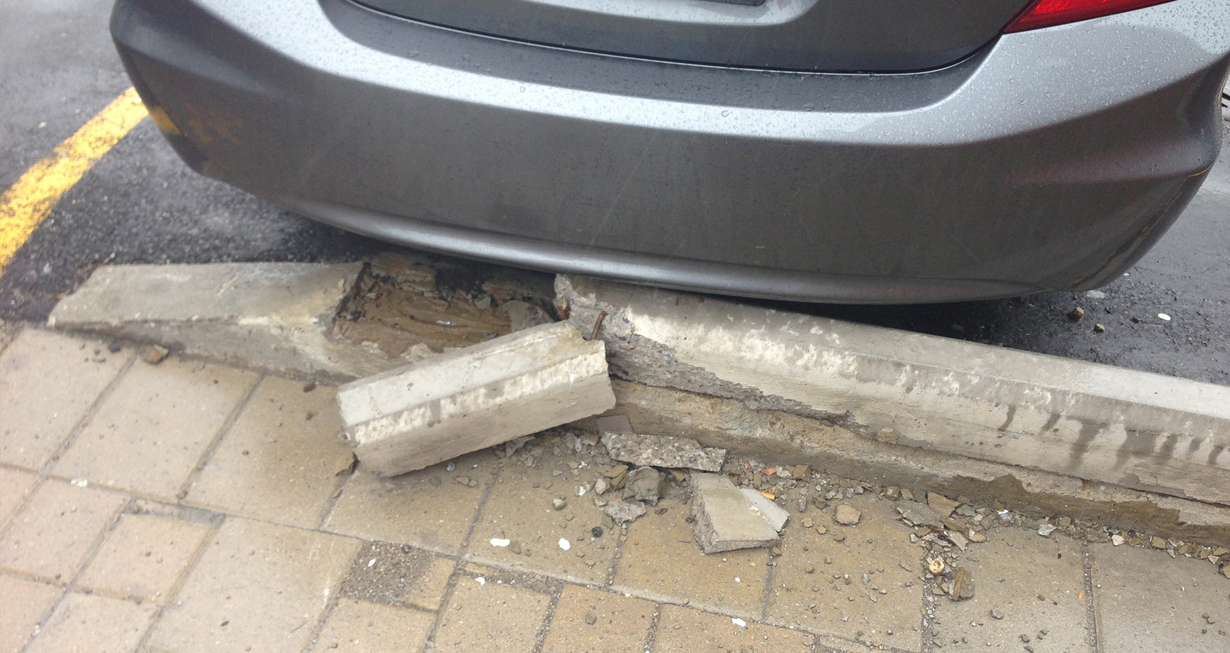
Rebar or mesh-enforced concrete is good for things like parking lot blocks and roads, but it still fails before it ought to. In fact, it usually has to crack before the rebar can chip in any of its tensile strength.

In high-stress concrete applications like bridges and skyscrapers, it’s terrifically important to avoid deflection — that’s when a concrete member flexes and bends under load. Deflection can cause the modern glass skins to pop off of skyscrapers, among other problems.

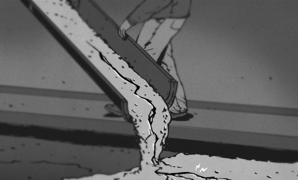
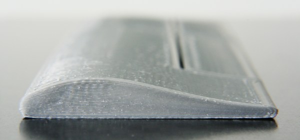
A solid, rigid bridge is much nicer to walk, drive, and bicycle on than a bridge that sways in the breeze. But how do you do make a rigid bridge? One solution is to apply stresses to the concrete before it ever bears the load of cars and trucks or a steady schedule of freight trains.

Pre-stressed concrete is like rebar-enforced concrete, but with the added power of tension baked in. By adding stress to the concrete before it goes into service, deflection will be reduced or perhaps eliminated altogether. With the addition of tensile strength, more of the concrete’s own strength is able to come into play.

Continue reading “A Good, Hard Look At Pre-Stressed Concrete”

Tensile Testing Machine Takes 3D Printed Parts To The Breaking Point

If you’re serious about engineering the things you build, you need to know the limits of the materials you’re working with. One important way to characterize materials is to test the tensile strength — how much force it takes to pull a sample to the breaking point. Thankfully, with the right hardware, this is easy to measure and  [CrazyBlackStone] has built a rig to do just that.

Built on a frame of aluminium extrusion, a set of 3D printed parts to hold everything in place. To apply the load, a stepper motor is used to slowly turn a leadscrew, pulling on the article under test. Tensile forces are measured with a load cell hooked up to an Arduino, which reports the data back to a PC over its USB serial connection.

It’s a straightforward way to build your first tensile tester, and would be perfect for testing 3D printed parts for strength. The STEP files (13.4 MB direct download) for this project are available, but [CrazyBlackStone] recommends waiting for version two which will be published this fall on Thingiverse although we didn’t find a link to that user profile.

Now we’ll be able to measure tensile strength, but the stiffness of parts is also important. You might consider building a rig to test that as well. Video after the break.

Continue reading “Tensile Testing Machine Takes 3D Printed Parts To The Breaking Point”

Measuring The Stiffness Of 3D-Printed Parts

How do you choose filament when you want strong 3D-printed parts? Like most of us, you probably take a guess, or just use what you have on hand and hope for the best. But armed with a little knowledge on strength of materials, you might be able to make a more educated assessment.

To help you further your armchair mechanical engineer ambitions, [Stefan] has thoughtfully put together this video of tests he conducted to determine the stiffness of common 3D-printing plastics. He’s quick to point out that strength and stiffness are not the same thing, and that stiffness might be more important than strength in some applications. Strength measures how much stress can be applied to an element before it deforms, while stiffness describes how well an element returns to its original state after being stressed. The test rig [Stefan] built for the video analyzes stiffness by measuring the deflection of printed parts under increasing loads. Graphing the applied force versus the deflection gives an indication of the rigidity of the part, while taking the thickness of the material into account yields the bending modulus. The results are not terribly surprising, with polypropylene being the floppiest material and exotic composite filaments, like glass fiber or even “nanodiamond” reinforced PLA coming out as the stiffest. PLA, the workhorse filament, comes in around the middle of the pack.

[Stefan] did some great work here, but as he points out, in the final analysis it almost doesn’t matter what the stiffness and strength of the filament are since you can easily change your design and add more material where it’s needed. That only works up to a point, of course, but it’s one of the many advantages of additive manufacturing.

Continue reading “Measuring The Stiffness Of 3D-Printed Parts”

3D Printering: Non-Planar Layer FDM

Non-planar layer Fused Deposition Modeling (FDM) is any form of fused deposition modeling where the 3D printed layers aren’t flat or of uniform thickness. For example, if you’re using mesh bed leveling on your 3D printer, you are already using non-planar layer FDM. But why stop at compensating for curved build plates? Non-planar layer FDM has more applications and there are quite a few projects out there exploring the possibilities. In this article, we are going to have a look at what the trick yields for us.

Continue reading “3D Printering: Non-Planar Layer FDM”

Tire assembly room of the Brunswick Tire Corporation

Retrotechtacular: Brunswick Shows A Bias For Tires

Somewhere between the early tires forged by wheelwrights and the modern steel-belted radial, everyone’s horseless carriage rode atop bias-ply tires. This week’s film is a dizzying tour of the Brunswick Tire Company’s factory circa 1934, where tires were built and tested by hand under what appear to be fairly dangerous conditions.

It opens on a scene that looks like something out of Brazil: the cords that form the ply stock are drawn from thousands of individual spools poking out from poles at jaunty angles. Some 1800 of these cords will converge and be coated with a rubber compound with high anti-friction properties. The resulting sheet is bias-cut into plies, each of which is placed on a drum to be whisked away to the tire room.

Continue reading “Retrotechtacular: Brunswick Shows A Bias For Tires”

Retrotechtacular: The (Long, Arduous) Birth Of A Tank

Throughout the 1950s and early 1960s, the United States Army provided regular status reports to both its interior members and the American public through a half-hour documentary television show called The Big Picture. Since the program was produced by the government, every episode immediately entered the public domain. This particular report tells the story of the T-48 project that culminated in the 90mm M48 Patton tank.

The film opens by providing a brief history of tanks and the lessons learned about them between WWI and the Korean War. The Army sought a more robust vehicle that could handle a wide variety of climates and terrain, and so the process of information gathering began. After a series of meetings at the Pentagon in which all parties involved explored every facet, the project was approved, and a manila folder was officially designated to the project and labeled accordingly.

vessels
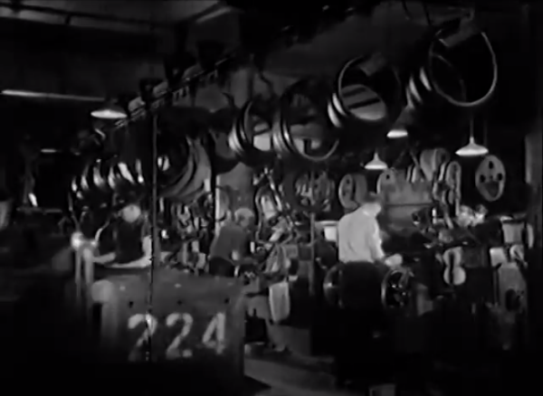
We then tour the R&D facility where new tank materials and components are developed and tested. It is here that the drive gears are put through their paces on a torsion machine. Air cleaners are pitted against each other to decide which can filter out the finest dust and sand. After careful analysis, different tank shell materials are test welded together with various, well-documented electrodes, and these panels are taken outside so their welds can be directly fired upon.

Continue reading “Retrotechtacular: The (Long, Arduous) Birth Of A Tank”